General Information
Figure 1 shows an entrance pavilion.
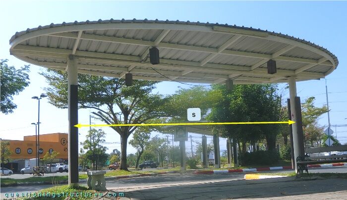
The steel structure consists mainly of two columns, a girder (placed over the columns), two cantilever single-layer roof grids (dashed lines), and metal roofing sheets. The columns are made of circular hollow sections, the girder is made of an I-section, and the grid is made of rectangular hollow sections. The distance between the columns s ≅ 5 m.
Cantilever Connection
Figure 2 shows the pavilion viewed from below.
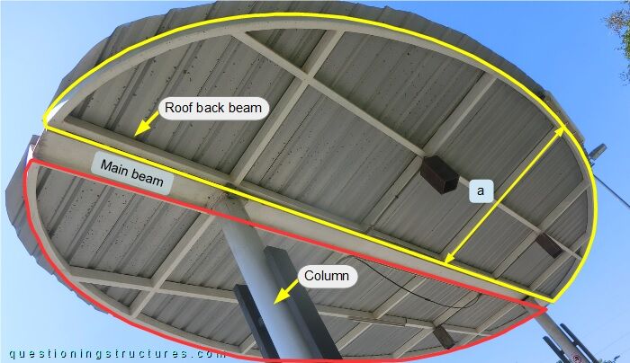
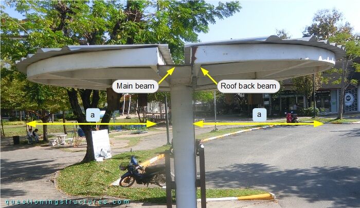
A grid carries a half-elliptical roofing sheet surface; the maximal cantilever arm a ≅ 1.5 m. The connection between the grid and the girder and the connection between the girder and the column are shown in figure 3.
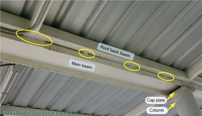
The perimeter beam of the grid is connected to the girder by intermittent welding (yellow rectangles); the girder lies on the weak axis and is connected to the column by a cap plate (weld connections). Figure 4 shows a lateral view of the roof.
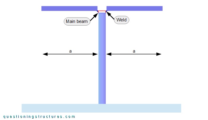
The bottom edge of the perimeter beam is placed on the girder's web elevation level, and the top edge is on a higher elevation than the girder. A schematic lateral view is shown in figure 5.
The intermittent welds are placed on the bottom edges and on the flanges' top elevation levels. The green arrow represents a force (F) placed at the maximal cantilever arm (a).
What types of stresses is the girder subjected to, and how are they distributed?
How stiff is the cantilever connection? What are some possible problems?