General Information
Figure 1 shows a covered logistic area.
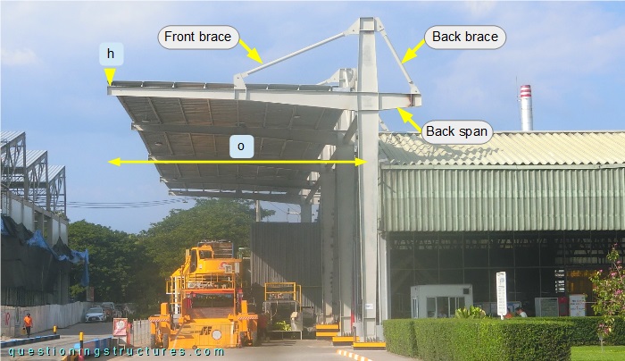
The main steel transverse structure consists of columns, braced cantilevers, and braced back spans. The columns, the cantilevers, and the back spans are made of I-sections, while the braces are made of circular hollow sections. The braced cantilever o ≅ 8 m, and the elevation h ≅ 9 m.
Braced Cantilever Structure
Figure 2 shows the structure.
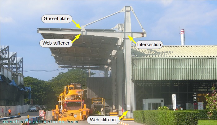
The cantilever and the back span are welded to the column; the connections to the braces consist of gusset plates and bolts (one bolt per gusset plate). Web stiffeners are installed under the gusset plates, in the intersection, and in the bottom region of the column. The intersection has the greatest cross-section; the column is tapered toward the top and the base; the cantilever is tapered toward the front brace connection, after which it is non-tapered until the free end; the back span is tapered toward the back brace connection. Figure 3 shows a schematic lateral view of the structure.
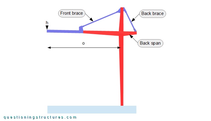
The tapered geometry is shown in red.
How does tapering the column toward its base affect the structural efficiency?
Figure 4 shows a schematic lateral view of the structure and an alternative variant.
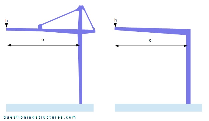
The alternative variant consists of a half-portal frame; the cantilever is tapered, while the column is non-tapered.