General Information
Figure 1 shows a farm hut.
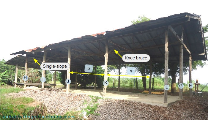
The timber structure consists mainly of columns (capital letters), a gable roof structure, knee braces, and an attached single-slope unit; the roof cladding is made of corrugated zinc sheets. There are four bays; the spacing b ≅ 3 m, and the span s ≅ 6 m. The structural members are connected by nails.
Alternative Load Path
Figure 2 shows a schematic layout of the structure.
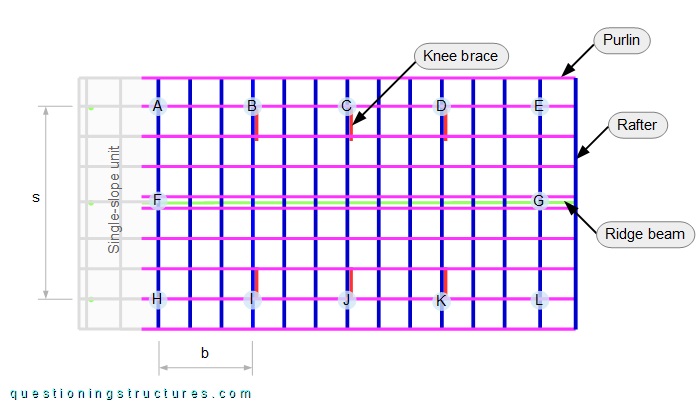
Knee braces are installed on columns B, C, D, I, J, and K. Figure 3 shows a structure sector.

The tie beam and the knee brace in the column J region and the tie beam in the column K region are damaged (locations indicated with X). Figures 4 and 5 show the damaged members.
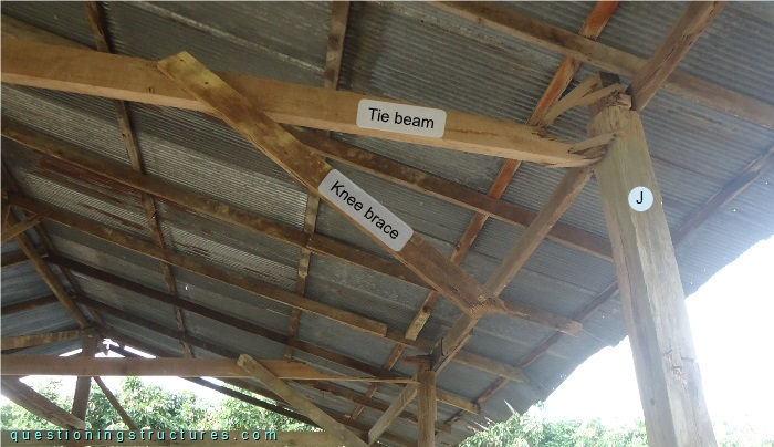
The tie beam and the knee brace are not structurally connected to the column.
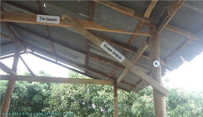
The tie beam is not structurally connected to the column.
Figure 6 shows two schematic cross-sections located at the damaged members, while figure 7 shows a schematic three-dimensional view of the farm hut.
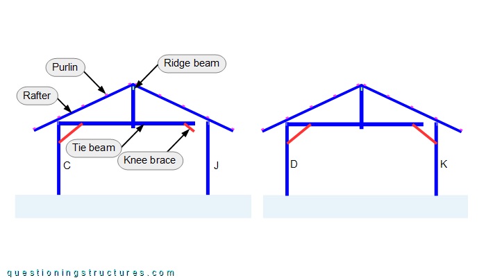
The ridge beam and the purlins are continuous, and the rafter spacing is about one meter.
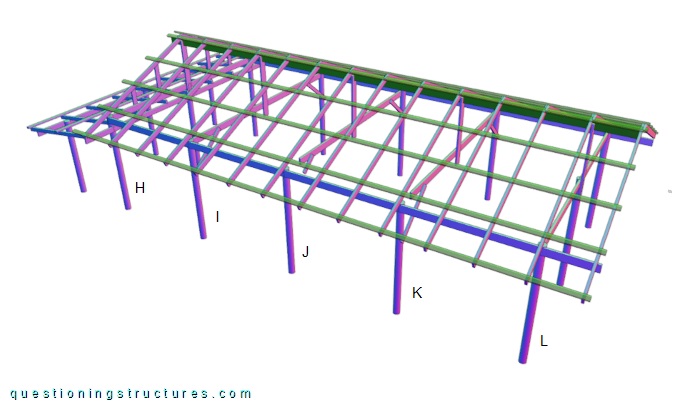
The alternative load path (due to the damaged members) did not cause a collapse.
Was the load case with the above shown damaged members analyzed in the design phase?
Figure 8 shows a schematic three-dimensional view of the farm hut with two bays instead of four.
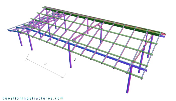
The spacing e ≅ 6 m. Suppose that the knee brace and the tie beam near the central column (J) are damaged as previously shown.
When are load cases with failed members required in the design phase?