General Information
Figure 1 shows a steel arch bridge that is used by motorcycles, bicycles and pedestrians.
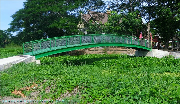
| Number of spans | 1 |
| Main span | ≅ 15 m |
| Arch rise | ≅ 1 m |
| Deck width | ≅ 2 m |
Support Types
Figure 2 shows the bridge.
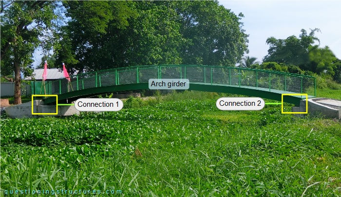
The arch girder has an I-section; the connections (1 and 2) to the RC abutments are shown in figures 3 and 4, respectively.
| Side view | Front view |
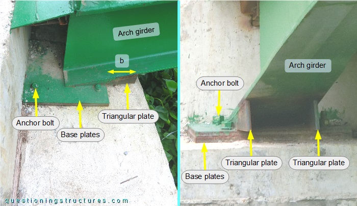
The arch girder is connected to the abutment by two stacked base plates, four anchor bolts, and two triangular plates that are welded under the flange; the length (b) cantilevers.
| Side view | Front view |
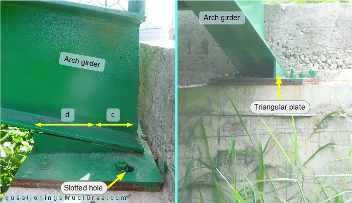
Connection 2 differs from connection 1; the arch girder is placed near the back edge of the base plates, and there is only one triangular non-cantilever plate that connects the flange over a length of c; there is no connection over a length of d. The stacked base plates have two longitudinal slotted holes. Figure 5 shows a schematic layout of connections 1 and 2.
| Connection 1 | Connection 2 |
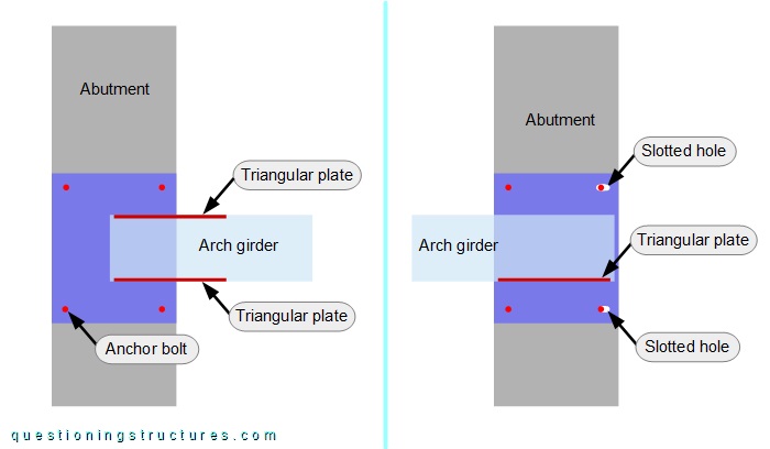
What type of support can be used for connections 1 and 2?
Plastic Deformation
Figure 6 shows the bridge.
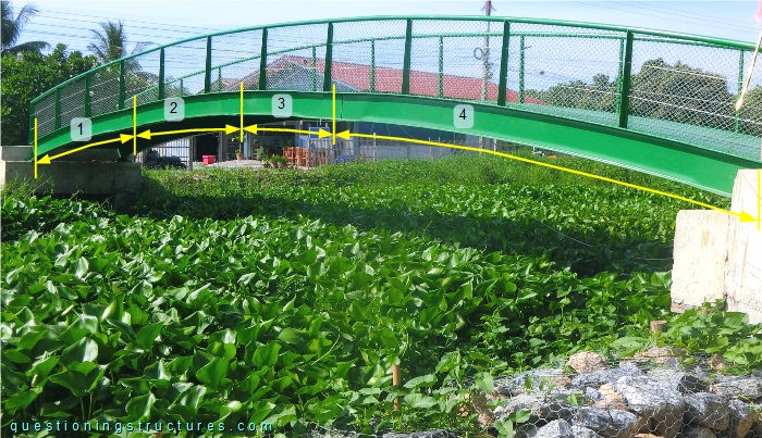
The arch girder is made of four welded I-sections (1 to 4). Sections 1, 2, and 3 are about a sixth main span long, while section 4 is about a half main span long.
The I-section-to-I-section connections are shown in figures 7 to 9.
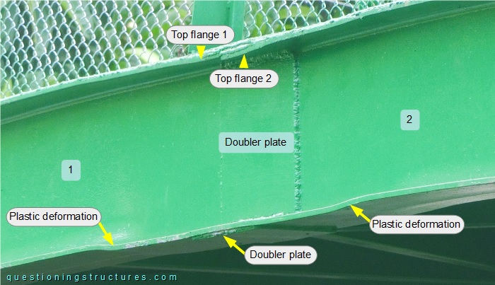
The connection has vertical and horizontal doubler plates. Plastic deformation located in the top and bottom flanges of both I-sections is noticeable.
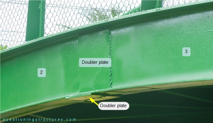
There is no plastic deformation.
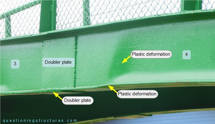
Plastic deformation located in the bottom flange and web region on I-section 4 is noticeable.
Bridge Entrances
The bridge entrances are shown in figures 10 and 11, respectively.
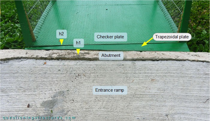
There is a trapezoidal gap between the abutment and the deck that is covered by a trapezoidal steel plate. The abutment and the edge of the checker plate are about at the same elevation level (h1 ≅ h2).
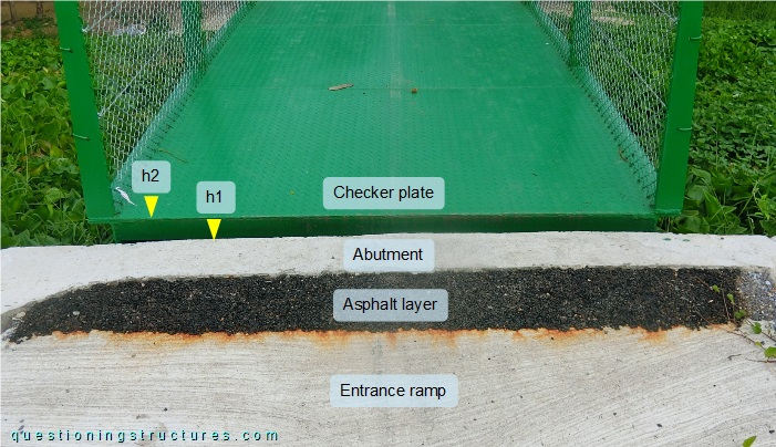
The abutment and the edge of the checker plate are on different elevation levels (h2 > h1), and there isn't a trapezoidal gap between them. There is also an elevation difference between the entrance ramp and the abutment, which is bridged by a sloped asphalt layer.