General Information
Figure 1 shows a two-lane road beam bridge.
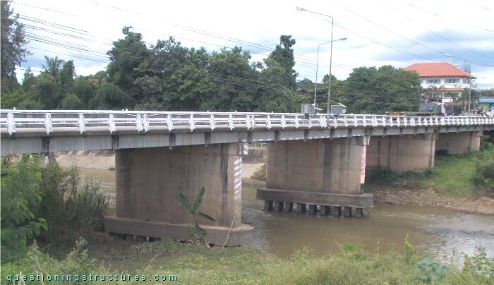
| Main span | ≅ 20 m |
| Girder | Precast concrete box-beam |
Transverse Tie Rods
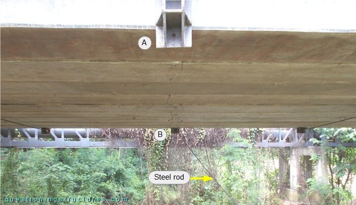
Figure 2 shows a main span sector viewed from below.
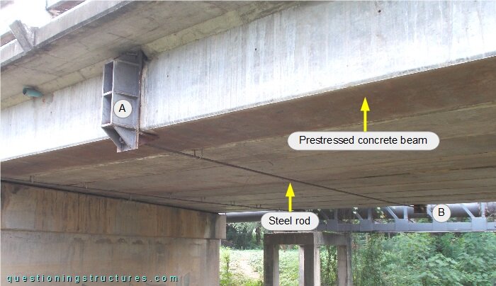
The girders are transversely tied by rod pairs (upper and bottom).
Figure 3 shows a transverse tie rod pair with a missing bottom tie connection.