General Information
Figure 1 shows a one-lane steel beam bridge that is used by non-heavy vehicles.
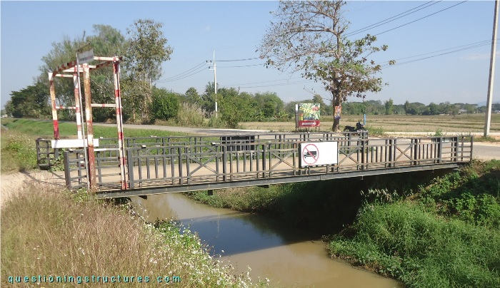
| Main span | ≅ 12 m |
| Girder | Steel I-section |
Bridge Configuration
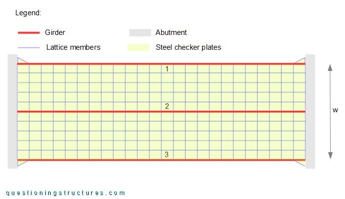
Figure 2 shows the bridge.
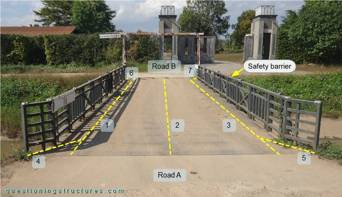
The bridge connects two parallel roads perpendicularly. The girder arrangement consists of three longitudinal (1 to 3) and four side (4 to 7) members; the latter are connected to the abutments and members 1 and 3. The safety barriers are welded over the deck that consists of steel checker plates. The deck is welded to the girders and a lattice non-stacked (framed) structure that consists of floor beams and stringers, as shown in the schematic layout in figure 3.
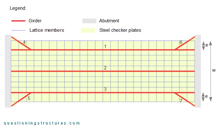
The width w ≅ 4 m, and the offset e ≅ 0.6 m.
Figure 4 shows a bottom view of the bridge.
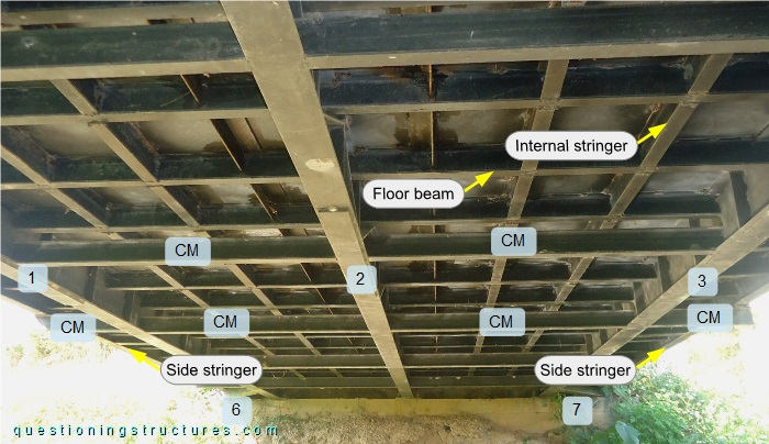
Under the lattice structure are installed cross members (CM) with a constant spacing (about 1.5 m); they are connected to girders 1 to 3 and the side stringers, as shown in figure 5.
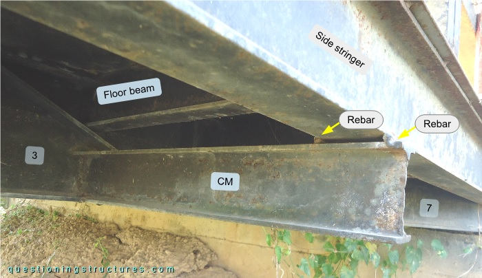
There is a gap between the cross member (CM) and the side stringer; two rebars are placed in the gap and connected by welding. The cross members (CM), the floor beams, and the internal stringers have approximately the same depth, while the side stringers have a greater depth.
Figure 6 shows a variant with a different girder arrangement.
The girder arrangement consists of three longitudinal members without an offset.
Span-to-Depth Ratio
Figure 7 shows a bottom view of the bridge.
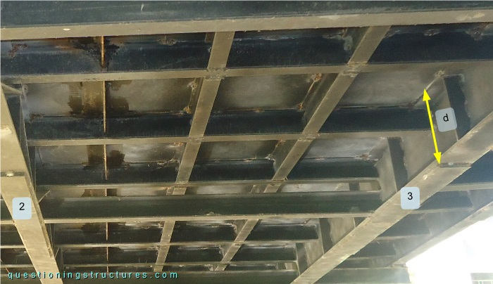
The girders have a depth d ≅ 25 cm; girders 1 to 3 are web-stiffened, and the main span is about 12 m; that gives a span-to-depth ratio of 48.