General Information
Figure 1 shows a cable-stayed bridge that is used by motorcycles, bicycles and pedestrians.
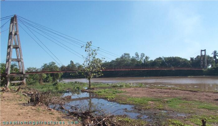
| Type | Single-span cable-stayed bridge |
| Main span | ≅ 140 m |
| Deck width | ≅ 2 m |
| Girder | Steel twin I-girder |
| Pylon | Reinforced concrete (A-type, longitudinal) |
| Stay cable arrangement | Radial (two cable planes) |
Anchorage Failure
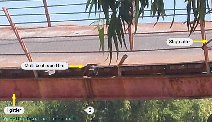
Figure 2 shows half main span.
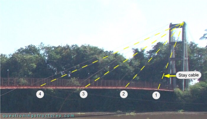
The girder anchorages are marked by the numbers. Figure 3 shows half main span without anchorage 2.
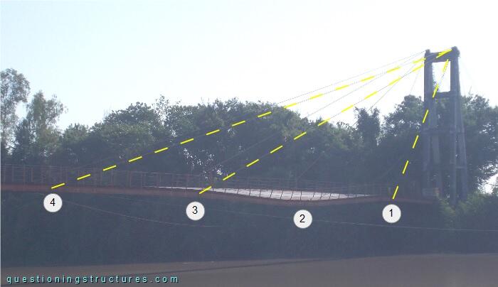
The failure (on one side only) did not cause a progressive collapse. Figure 4 shows a side view of the girder deformation without anchorage 2, while figure 5 shows a schematic three-dimensional view of an anchorage.
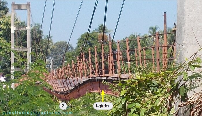
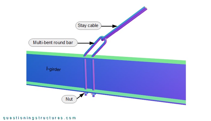
The anchorage consists of a multi-bent steel round bar that passes through upper and bottom flange holes and two nuts. Figure 6 shows a side view of the failed anchorage.
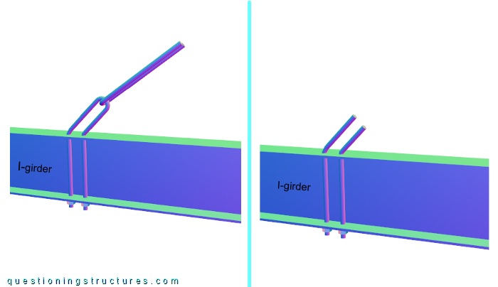
The failure is located at the 180-degree U-bent start region. Figure 7 shows a schematic three-dimensional view of the unfailed and failed anchorage.
| Unfailed | Failed |
What are the main structural consequences?