General Information
Figure 1 shows a cable-stayed bridge that is used by motorcycles, bicycles and pedestrians.
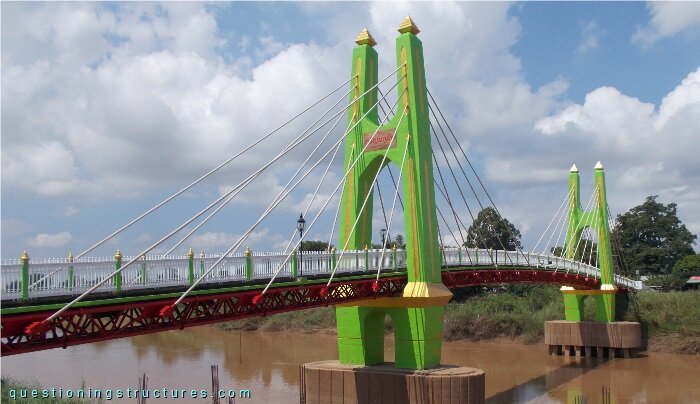
| Type | Three-span cable-stayed bridge |
| Main span | ≅ 50 m |
| Deck width | ≅ 2 m |
| Girder | Steel truss |
| Pylon | Reinforced concrete |
| Stay cable arrangement | Fan (two cable planes) |
Truss Girder
Figure 2 shows the bridge.
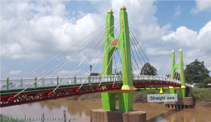
The truss girder girder has a slightly curvature and an isosceles trapezoidal cross-section, as shown in figure 3.
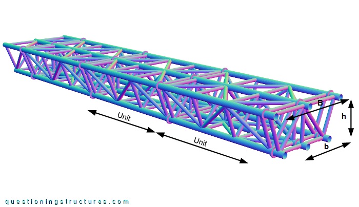
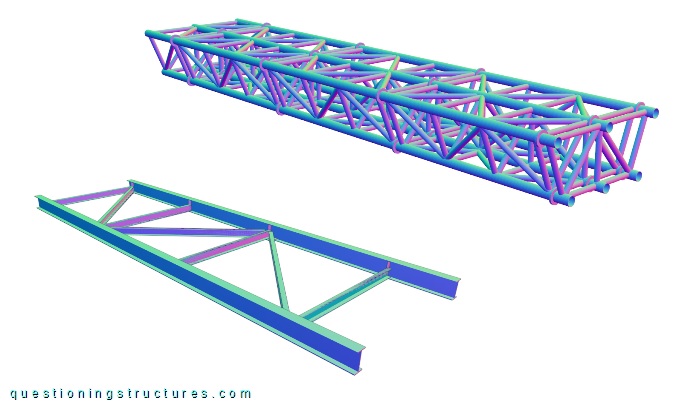
The truss in made of circular hollow sections and consists of three upper chords, three bottom chords, diagonals, verticals, cross members, and cross braces. The upper base B ≅ 2 m, the bottom base b ≅ 1.4 m, and the height h ≅ 0.8 m. The truss consists of several units that are connected by bolted circular end-plates, as shown in figure 4.
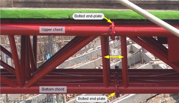
The truss does not have diagonals, cross members, and cross braces in the connection region; the verticals' spacing (l) is shorter. Figure 5 shows the used truss girder and a braced twin I-girder as an alternative variant.
Stay Cable Bending
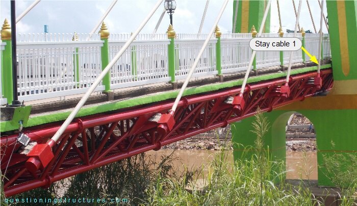
Figure 6 shows a side span.
The girder anchorage of stay cable 1 viewed from above is shown in figure 7.
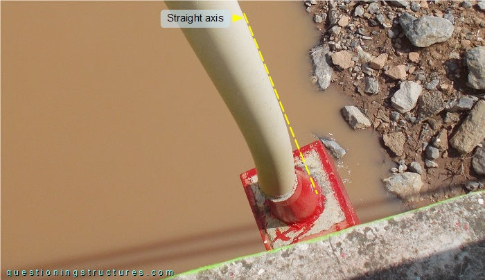
The girder anchorage is fixed, and stay cable bending is noticeable.
What are the main consequences?