General Information
Figure 1 shows a cable-stayed bridge that is used by motorcycles, bicycles and pedestrians.
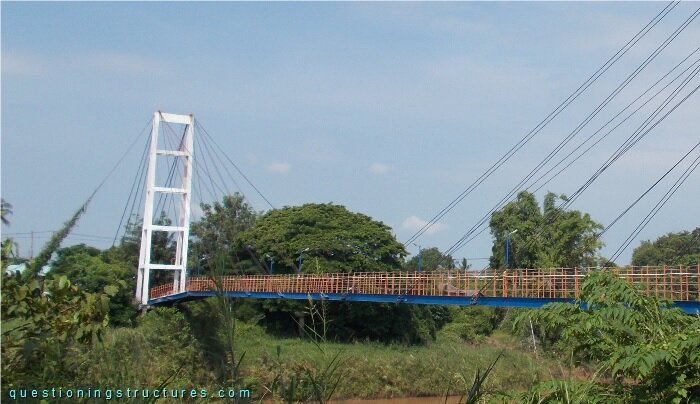
| Type | Single-span cable-stayed bridge |
| Main span | ≅ 120 m |
| Deck width | ≅ 2 m |
| Girder | Steel twin I-girder |
| Pylon | Reinforced concrete (A-type, longitudinal) |
| Stay cable arrangement | Radial (two cable planes) |
Main Span Vertical Alignment
Figure 2 shows a side view of the main span.
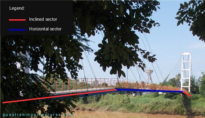
The main span vertical alignment consists of one horizontal and two inclined sectors; the former is located in the mid-span region. Figure 3 shows a schematic lateral view of half bridge.
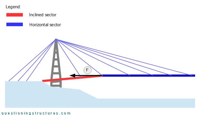
The black arrow represents the horizontal component force (F) caused by the stay cables in the horizontal sector.
Sagging of Stay Cables
Figure 4 shows a schematic lateral view of the bridge.
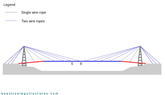
A stay cable in the horizontal sector consists of two steel wire ropes, while a stay cable in the inclined sector consists of a single wire rope. Figure 5 shows stay cables 5 and 6 viewed from the main span.
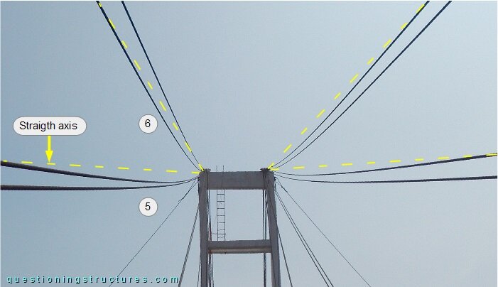
Stay cables 5 and 6 are sagging. Video 1 shows stay cable 6 during hand-induced vibration.
Deck Materials
Figure 6 shows the deck viewed from the main span.
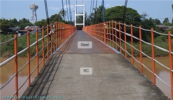
The deck in the inclined sector is made of reinforced concrete (thickness ≅ 8 cm); in the horizontal sector, of steel checker plates (thickness ≅ 0.5 cm).