General Information
Figure 1 shows a cable stayed-bridge that is used by motorcycles, bicycles and pedestrians.
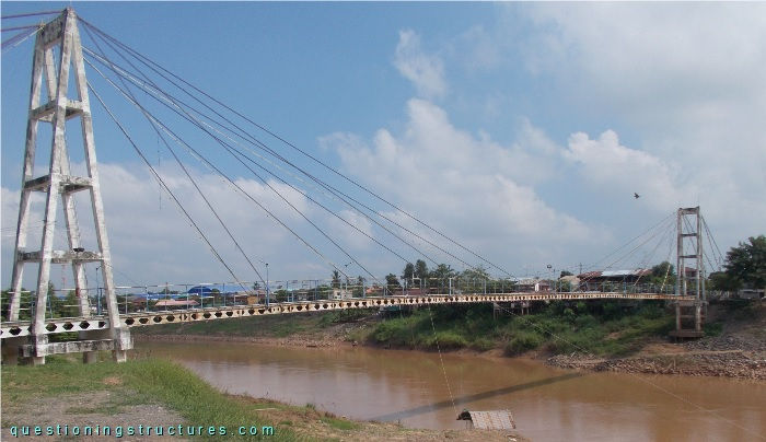
| Type | Single-span cable-stayed bridge |
| Main span | ≅ 100 m |
| Deck width | ≅ 2 m |
| Girder | Steel twin castellated I-beam |
| Pylon | Reinforced concrete (A-type, longitudinal) |
| Stay cable arrangement | Radial (two cable planes) |
Castellated I-Beams
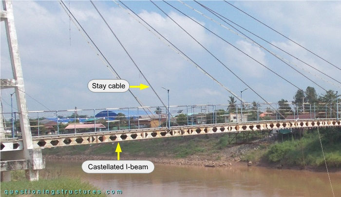
Figure 2 shows a side view of a main span sector.
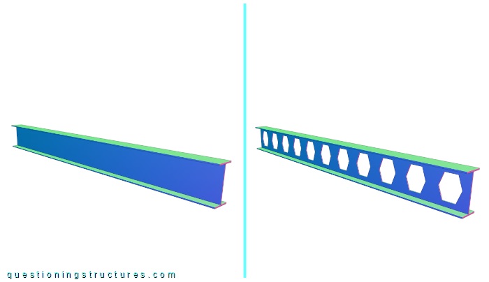
The castellated I-beam has hexagonal openings. Figure 3 shows a schematic three-dimensional view of an I-beam and a castellated I-beam with hexagonal openings.
| Standard | Castellated |
What are some possible reasons for using castellated I-beams for the above shown bridge?
Load Case
Figure 4 shows a side view of a main span sector.
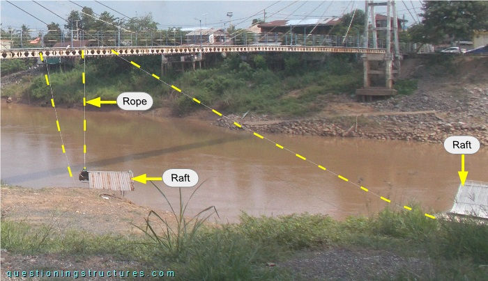
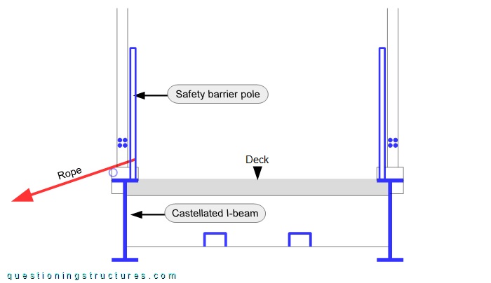
Two rafts are moored at the bridge by ropes. Figure 5 shows a connection between a rope and the bridge.
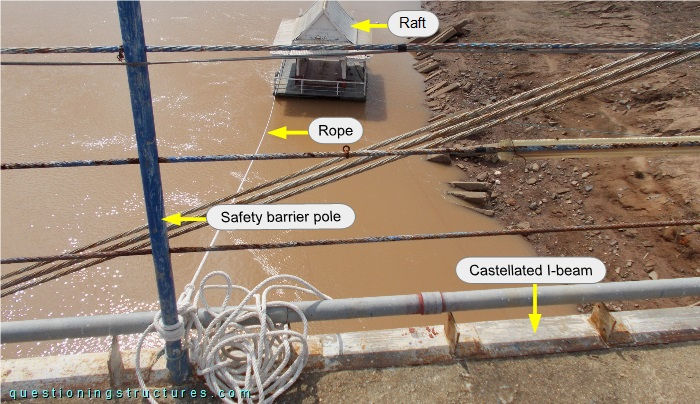
The rope is connected to the castellated I-beam by the safety barrier pole. Figure 6 shows a schematic cross-section of the bridge.