General Information
Figure 1 shows a cable-stayed bridge that is used by motorcycles, bicycles and pedestrians.
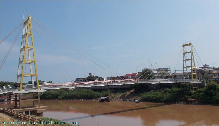
| Type | Single-span cable-stayed bridge |
| Main span | ≅ 90 m |
| Deck width | ≅ 2.5 m |
| Girder | Steel twin I-girder |
| Pylon | Reinforced concrete (A-type, longitudinal) |
| Stay cable arrangement | Radial (two cable planes) |
A-Type Pylon
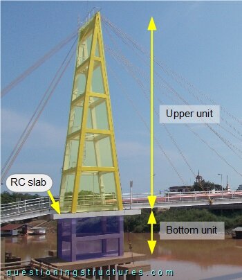
Figure 2 shows a side view of a pylon.
The A-structure is aligned to the longitudinal axis of the bridge. Figure 3 shows a schematic three-dimensional view of the used pylon and a portal-type pylon made of RC.
| A-type, longitudinal | Portal-type |
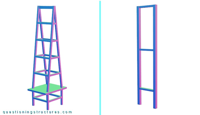
What are some possible reasons to use the above shown A-type instead of a portal-type pylon?
Each pylon has two lateral stay cables (one per side), as shown in figure 4.
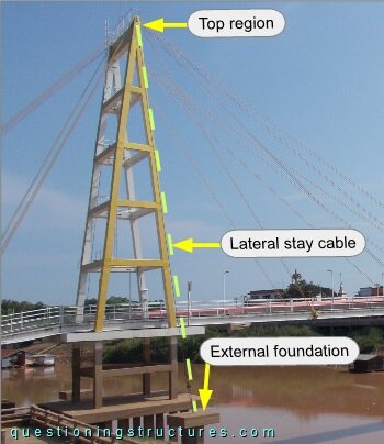
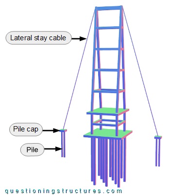
Each lateral stay is anchored to the pylon top-end region and an external foundation, which consists of a pile cap and two piles. The same foundation type is used for the pylon. Figure 5 shows a schematic three-dimensional view of the pylon with lateral stay cables and foundations.
The lateral stay cables anchorages are shown in figure 6.
| Pylon top region | External foundation |
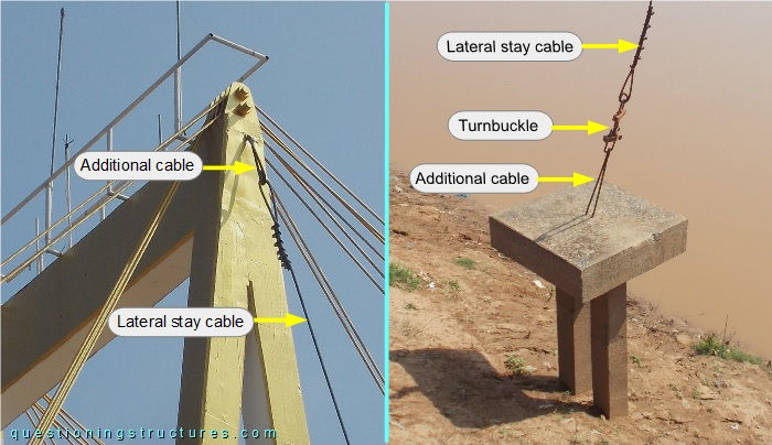
The pylon top-end region is anchored by an additional cable, while the external foundation is anchored by a turnbuckle and an additional cable.
Figure 7 shows a side view of the pylon region.
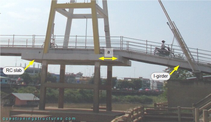
A reinforced concrete slab is installed between the vertical and the A-structure of the pylon. The slab cantilevers on each side, and the cantilever longitudinal arm a ≅ 1 m. The I-girder of the approach span is connected to the free-end region of the slab. Figure 8 shows a schematic three-dimensional view of the pylon region.
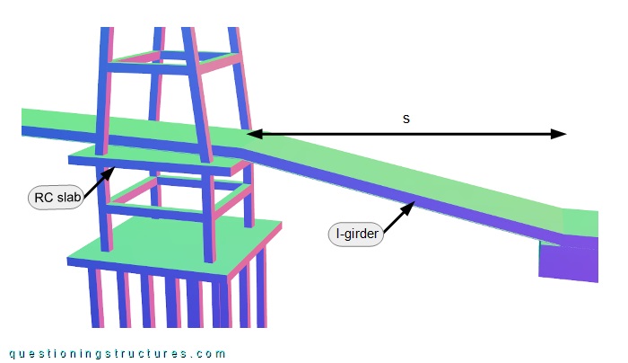
The approach span s ≅ 10 m.