General Information
Figure 1 shows a cable-stayed bridge that is used by motorcycles, bicycles and pedestrians.
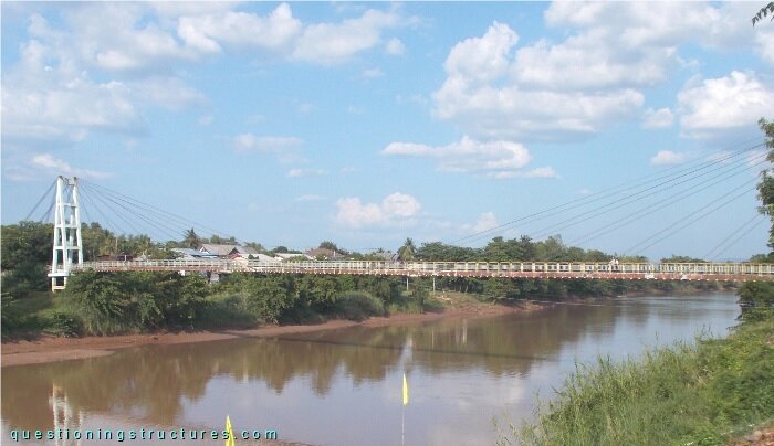
| Type | Single-span cable-stayed bridge |
| Main span | ≅ 130 m |
| Deck width | ≅ 2 m |
| Girder | Steel twin I-girder |
| Pylon | Reinforced concrete (A-type, longitudinal) |
| Stay cable arrangement | Radial (two cable planes) |
Lateral Cables
Figure 2 shows a schematic three-dimensional view of the bridge.
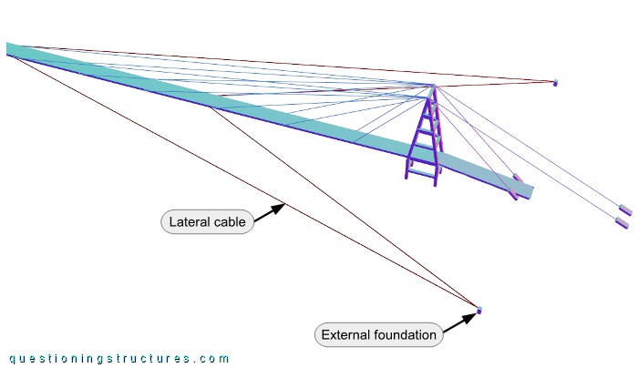
There are eight lateral cables; they are connected to the girder and four external foundations (a cable pair per foundation). The girder connections are located at approximately a quarter of the main span (s) and in the mid-span region. Figure 3 shows a lateral cable pair viewed from the mid-span region.
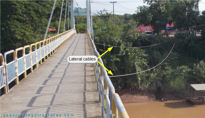
The lateral cables are sagging. The connections to the girder and to the external foundation are shown in figures 4 and 5, respectively.
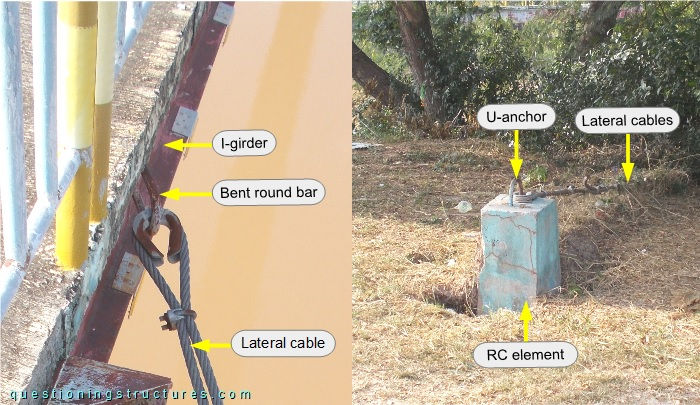
The web of the girder is connected by a bent round bar, and the cable termination consists of U-bolt clamps and a cable thimble.
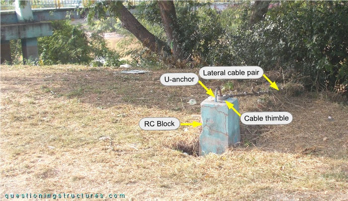
The external foundation is made of an RC block, and the lateral cable pair is connected to it by a U-anchor. The cable pair is terminated with U-bolt clamps and a single cable thimble.
When are lateral cables required for a cable-stayed bridge?
Anchor Blocks
Figure 6 shows the bridge entrance on shore 1.
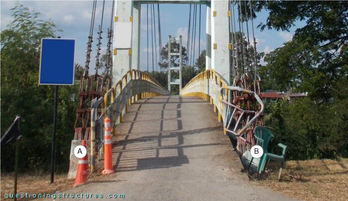
Anchor blocks A and B are shown in figures 6 and 7, respectively.
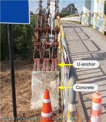
The anchor block is connected by U-anchors; the distance (a) is the non-embedded length.
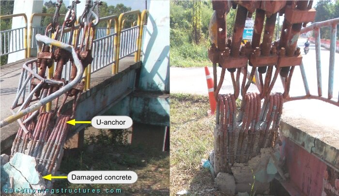
The anchor block is damaged, and the embedded U-anchor length is reduced.
Girder Deformation
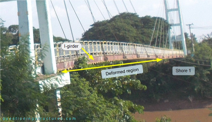
Figure 9 shows a side view of a main span sector viewed from shore 1.
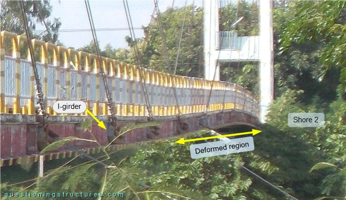
Girder deformation near shore 2 is noticeable. Figure 10 shows the deformed region viewed from shore 2.
What are the main structural consequences?