General Information
Figure 1 shows a cable-stayed bridge that is used by motorcycles, bicycles and pedestrians.
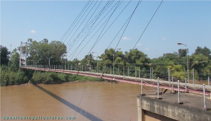
| Type | Single-span cable-stayed bridge |
| Main span | ≅ 125 m |
| Deck width | ≅ 1.5 m |
| Girder | Steel twin I-girder |
| Pylon | Reinforced concrete (A-type, longitudinal) |
| Stay cable arrangement | Radial (two cable planes) |
Grease Coating
Figure 2 shows a stay cable in the main span region.
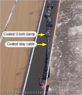
The stay cable (steel wire rope) and the U-bolt clamps are coated with grease. Figure 3 shows the anchorage region.
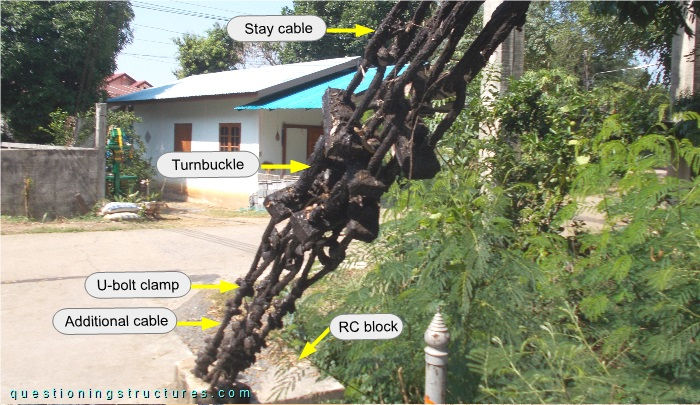
The stay cables are connected to the RC block by turnbuckles and additional cables terminated with U-bolt clamps. All structural members (except the RC block) are grease-coated. Two coated turnbuckles are shown in figure 4.
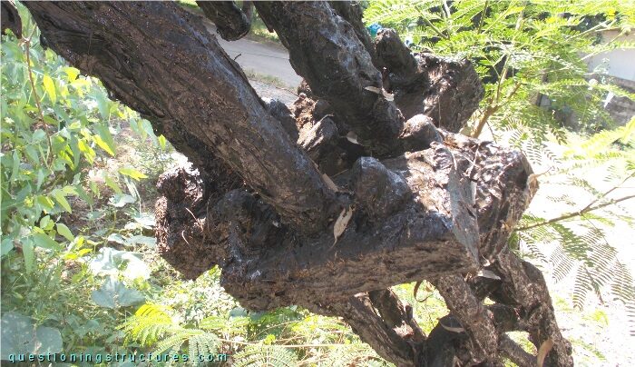
The coat layer is about 5 mm thick. Figure 5 shows the additional cables in the RC block region.
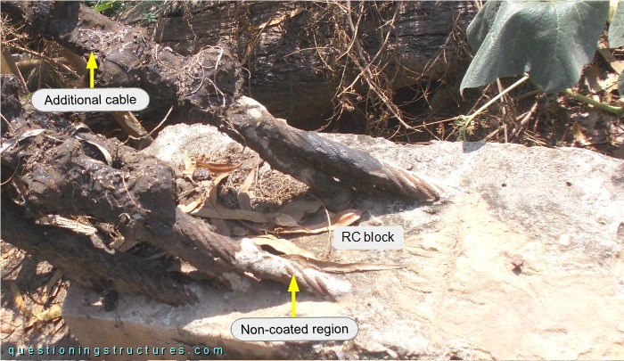
Non-coated regions near the concrete surface are noticeable.
What are some possible causes for the non-coated regions near the concrete surface?