General Information
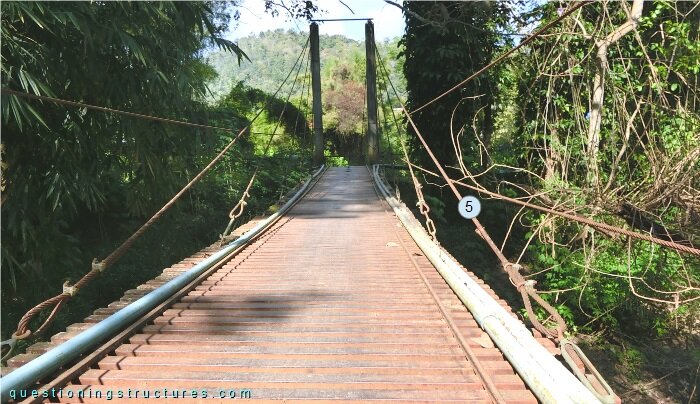
Figure 1 shows a cable-stayed bridge that is used by motorcycles, bicycles and pedestrians.
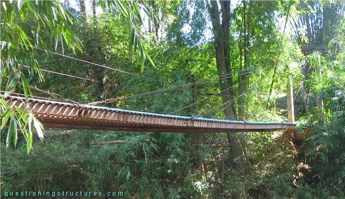
| Type | Single-span cable-stayed bridge |
| Main span | ≅ 27 m |
| Deck width | ≅ 1.5 m |
| Girder | Steel twin C-girder (cold formed) |
| Pylon | Reinforced concrete and steel |
| Stay cable arrangement | Radial (two cable planes) |
Arrangement of Stay Cables
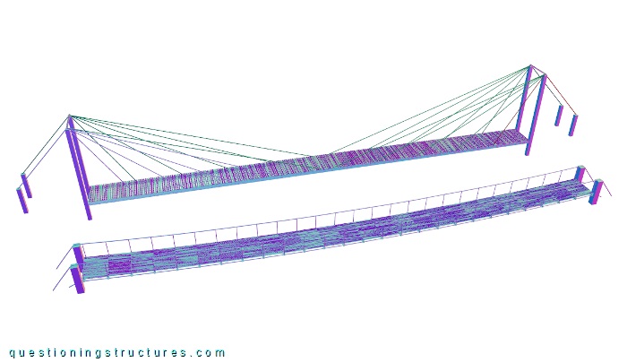
Figure 2 shows a schematic three-dimensional view of the bridge.
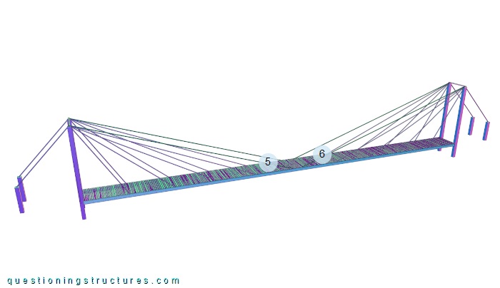
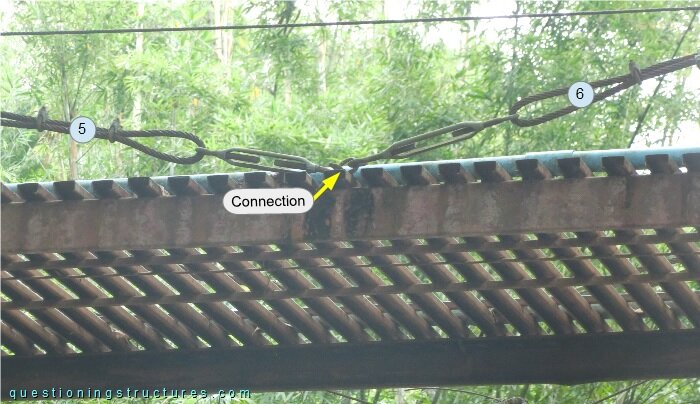
The bridge has 20 front and 4 back stays. Stay cables 5 and 6 are anchored to the girder at the same location, as shown in figure 3.
Girder Anchorages
Figure 4 shows a girder anchorage.
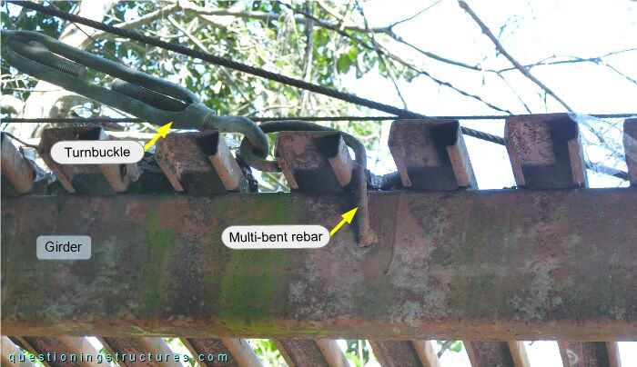
The anchorage consists of a turnbuckle (open body) and a multi-bent rebar. The girder has a web hole, through which the multi-bent rebar passes.
Figures 5 and 6 show two anchorages viewed from above.
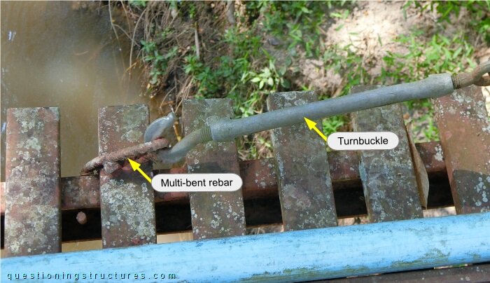
The multi-bent rebar has a closed hook, and the turnbuckle is of closed body type. The wire rope termination consists of U-bolt clamps with the U-parts positioned on the live end of the cable. The stay and the turnbuckle are directly connected (without a cable thimble).
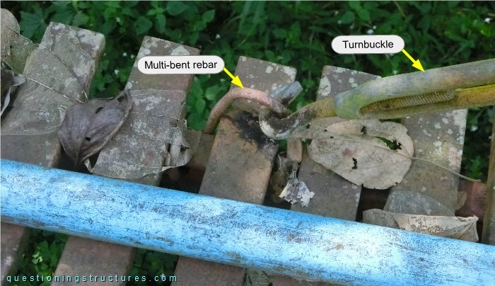
The multi-bent rebar has an open hook, and the turnbuckle is of open body type; the U-parts are alternately positioned.
Does anchorage 1 structurally behave like anchorage 2?
Pylon Anchorage
The stay cables are anchored to the pylon as shown in figure 7.
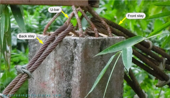
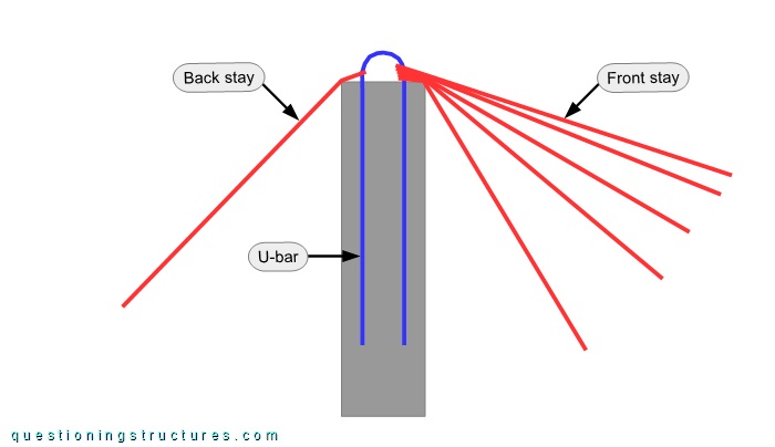
The stays are anchored to the pylon's top end by a U-anchor, and the front stays are stacked one on top of the other. Stays and the U-anchor are directly connected. Figure 8 shows a schematic cross-section of the anchorage region.
Stay Cable Vibration
Figure 9 shows the bridge viewed from the mid-span region.
The stay cables are sagging. Video 1 shows stay cable 5 during hand-induced vibration.
Suspended Bridge
A suspended bridge as an alternative variant and the used cable-stayed bridge are shown in figure 10.
What are some possible reasons for choosing the cable-stayed bridge instead of the suspended bridge?