General Information
Figure 1 shows a pedestrian cable-stayed bridge.
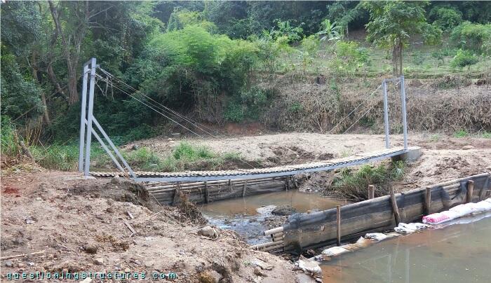
| Type | Single-span cable-stayed bridge |
| Main span | ≅ 12 m |
| Deck width | ≅ 0.8 m |
| Girder | Steel square hollow section |
| Pylon | Steel |
| Stay cable arrangement | Radial (two cable planes) |
Stay Cable Arrangement and Inclined Members
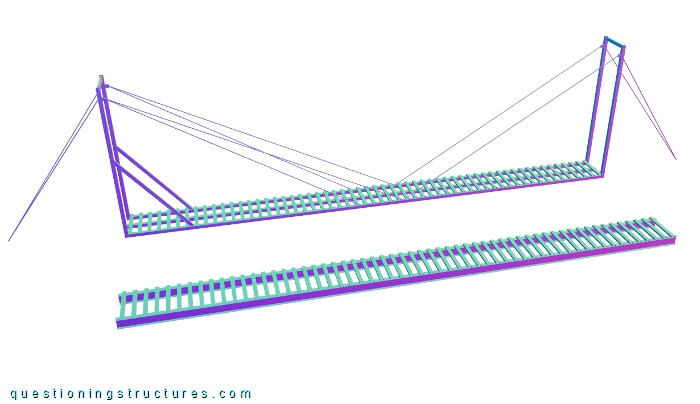
Figure 2 shows a schematic three-dimensional view of the bridge.
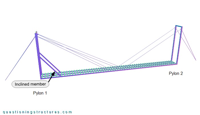
Pylon 1 is connected to two back and four front stays, while pylon 2 is connected to a pair of front and back stays. The back stays are inclined in two planes and converge toward the longitudinal axis of the bridge (black dashed line). Pylon 1 and the girder are also connected by two inclined members with a rectangular hollow cross-section.
What is the purpose of the inclined members?
Stay Cables
A cable plane is marked in figure 3.
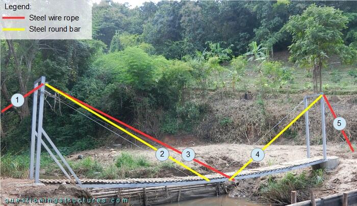
A cable plane consists of five stay cables: 1, 3, and 5 are made of a steel wire rope, while 2 and 4 are made of a steel round bar.
Stay Cables Anchorages
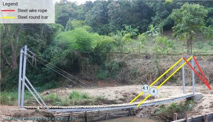
The stay cables are anchored to the girder as shown in figure 4.
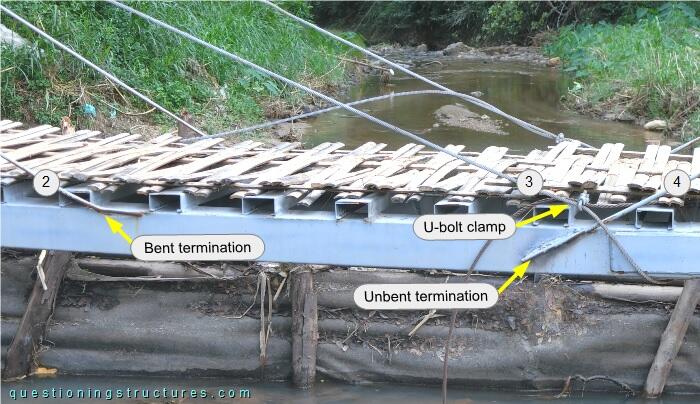
Stay cables 2 and 4 (round bars) are anchored to the girder by welding: stay cable 2 has a bent termination, while stay cable 4 has an unbent termination. Stay cable 3 (wire rope) is looped once around the girder; the termination consists of a single U-bolt clamp. Stay cables 3 and 4 are overlapping each other.
What is the purpose of overlapping stay cables 3 and 4?
Stay Cables Vibrations
Figure 5 shows the bridge.
Video 1 shows front stays 4 and 4.1 during hand-induced vibration.
The vibration amplitude of stay cable 4 is smaller than the vibration amplitude of stay cable 4.1.
Main Span Deflection
Figure 6 shows a side view of the bridge.
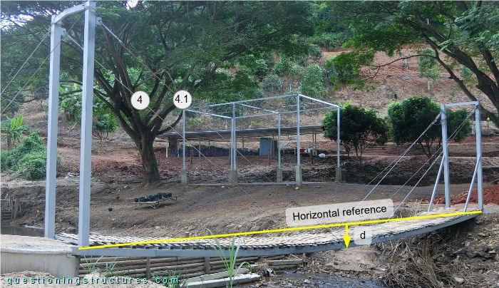
The vertical deflection in the mid-span region d ≅ 0.3 m.
Bridge Cross-Section
Figure 7 shows a schematic cross-section of the bridge.
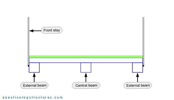
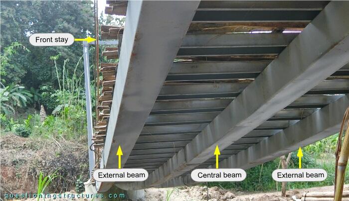
The girders (A, B, and C) are made of square hollow sections, and the front stays are anchored to girders A and C. Transverse C-channels with a constant spacing are placed over the girders, and the deck is made of bamboo lattice panels; the deck width is approximately 0.8 m. Figure 8 shows the bridge viewed from below.
Construction Phase
Figure 9 shows a bridge sector.
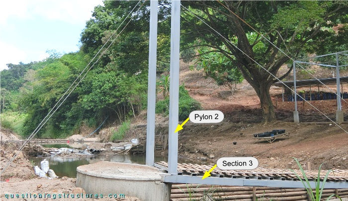
The pylons' columns are made of square hollow sections and are welded over girders A and C.
Efficient Span Range
Figure 10 shows a schematic three-dimensional view of the bridge and a beam bridge made of two I-girders and C-channel decking.
What are some possible reasons for choosing the used bridge instead of the beam bridge?