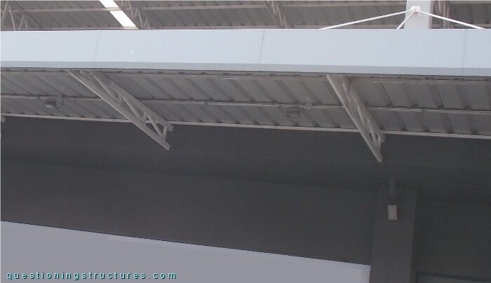
General Information
Figure 1 shows a steel canopy roof.
![Steel canopy roof.](canopy-roofs/structure-1/1-canopy-roof.jpg)
Trusses
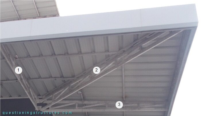
Figure 2 shows a truss.
![Steel truss of a canopy roof with main measures.](canopy-roofs/structure-1/2-truss.jpg)
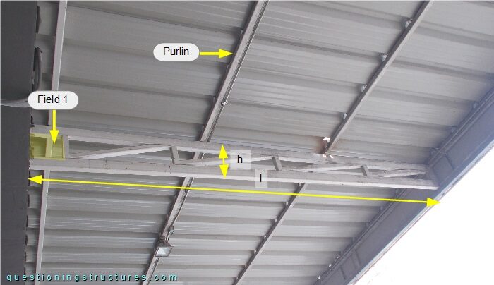
The length l ≅ 3.5 m, and the height h ≅ 0.4 m. Field 1 has a shorter length and no diagonal; the purlins are placed away from the truss nodes.
Purlins
Figure 3 shows the purlin layout.
![Purlin layout of a canopy roof viewed from below.](canopy-roofs/structure-1/3-purlin-layout.jpg)
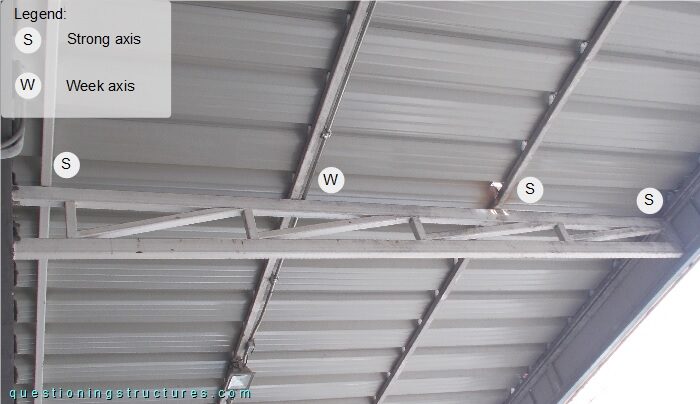
Three purlins are lying on the strong-axis, while one purlin lies on the week-axis.
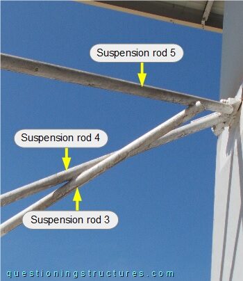
Suspension Rods
Figure 4 shows three suspension rods.
![Suspension rods of a canopy roof.](canopy-roofs/structure-1/4-suspension-rods.jpg)
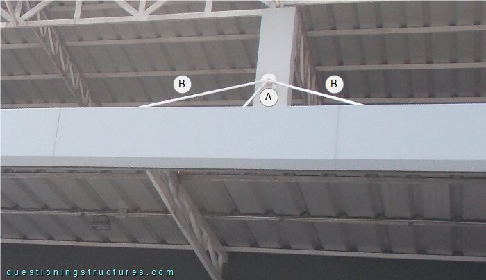
Suspension rod A is inclined in one plane, while suspension rods B are inclined in two planes.
Figure 5 shows a suspension rod to canopy roof connection viewed from below.
![Connection between suspension rod and canopy roof.](canopy-roofs/structure-1/5-suspension-rod-roof-connection.jpg)
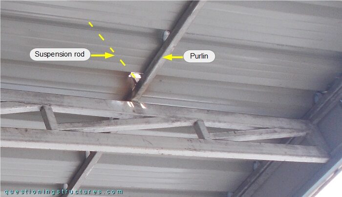
The suspension rod is connected to a purlin by welding.
Figure 6 shows a suspension rod to canopy roof connection viewed from above.
![Connection between suspension rod and canopy roof.](canopy-roofs/structure-1/6-suspension-rod-canopy-connection.jpg)
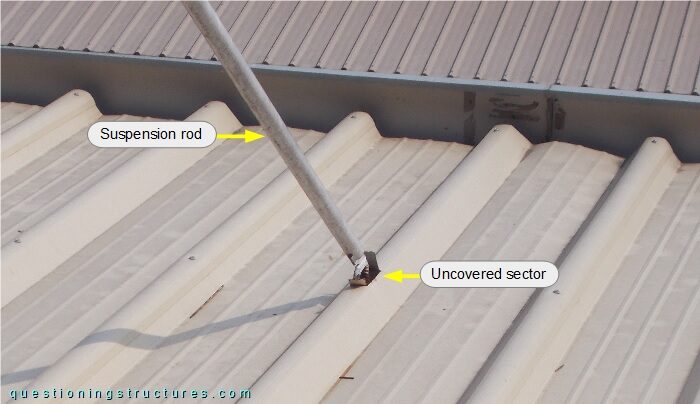
An uncovered roof sector is noticeable (also visible in figure 5).
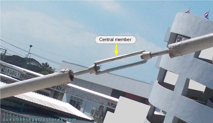
Figure 7 shows a suspension rod.
![Suspension rod with central member.](canopy-roofs/structure-1/7-suspension-rod.jpg)
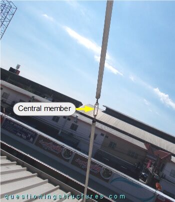
The suspension rod consists of two circular hollow profiles and a central member, as shown in figure 8.
![Central member of a suspension rod.](canopy-roofs/structure-1/8-central-member.jpg)
Corner Zone Trusses
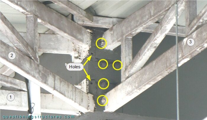
Figure 9 shows the corner zone viewed from below.
The corner zone consists of three trusses: a diagonal truss (2), and two perpendicular trusses (1 and 3). The trusses are connected to the reinforced concrete structure as shown in figures 10 and 11.
![Connections between steel trusses of a canopy roof and the reinforced concrete structure of a building in the corner region.](canopy-roofs/structure-1/10-trusses-rc-structure-connections.jpg)
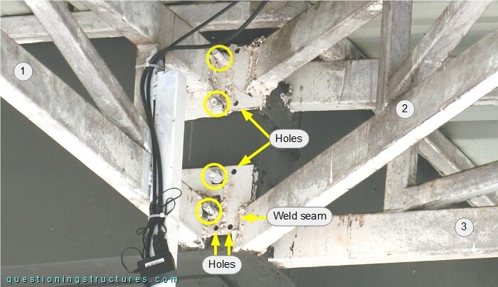
The trusses are connected to the reinforced concrete structure by holed end-plates and anchor bolts, which are marked by the yellow circles.
![Connections between steel trusses of a canopy roof and the reinforced concrete structure of a building in the corner region.](canopy-roofs/structure-1/11-trusses-rc-structure-connections.jpg)
Corner Zone Suspension Rods
Figure 12 shows the corner zone viewed from above.
![Suspension rods of a canopy roof in the corner zone viewed from above.](canopy-roofs/structure-1/12-corner-zone.jpg)
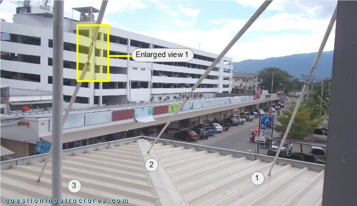
Enlarged view 1 is shown in figure 13.
![Suspension rod with deviation angle; structural problems.](canopy-roofs/structure-1/13-enlarged-view.jpg)
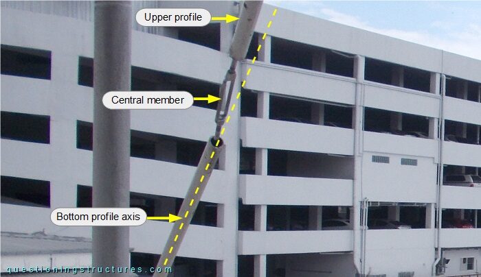
Upper and bottom profiles are not on the same axis.
Figure 14 shows a corner zone sector viewed from below.
![Suspension rods of a canopy roof in the corner zone viewed from below.](canopy-roofs/structure-1/14-corner-zone.jpg)
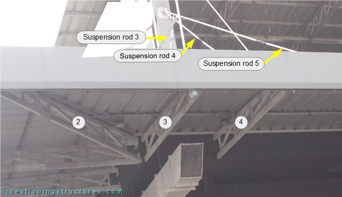
Suspension rod 3 is connected to suspension rods 4 and 5, as shown in figure 15.
![Connection between three suspension rods of a canopy roof; connection between suspension rods and the reinforced concrete column.](canopy-roofs/structure-1/15-suspension-rods-connections.jpg)