General Information
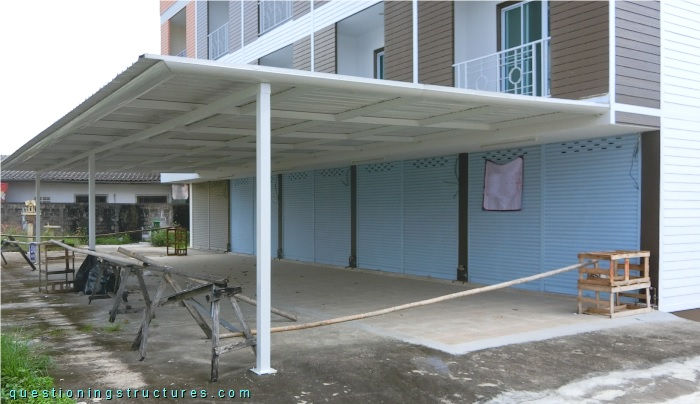
Figure 1 shows a steel canopy.
Canopy Roof Raising
Figure 2 shows a lateral view of the canopy roof.
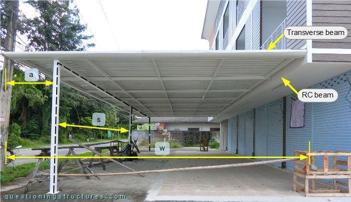
The roof structure consists of transverse beams, purlins, and metal roofing sheets. The transverse beams and purlins are made of rectangular hollow sections, and the floor system is framed. The transverse beams have an overhang of a; they are supported by a reinforced concrete beam of the building and by a two-bay portal frame (black dashed lines) made of square hollow sections. The width w ≅ 6 m, and a bay span s ≅ 8 m. The transverse beams are connected to the RC beam as shown in figure 3.
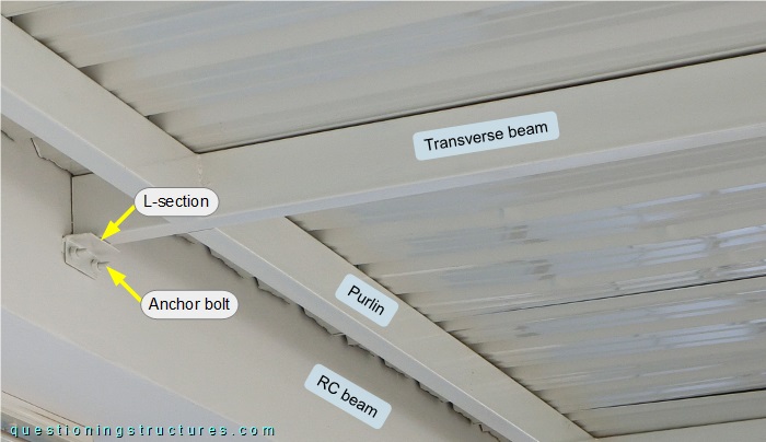
The transverse beam is welded over a short L-section, which is connected to the RC beam by two anchor bolts. Figure 4 shows a lateral view of the raised canopy roof.
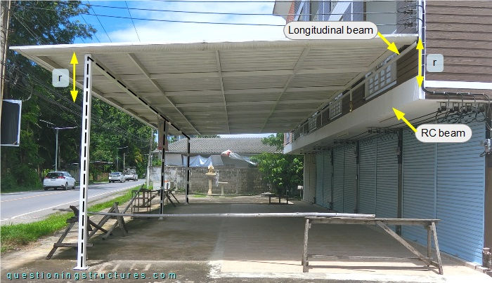
The raise r ≅ 0.6 m, and the two-bay portal frame is made of the same sections (type and size). The raised roof structure equals the unraised roof structure, except for the connection between the transverse beams and the building, which consists of a longitudinal beam made of a square hollow section, as shown in figure 5.
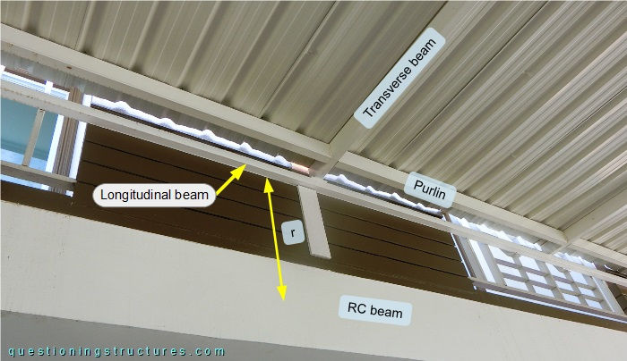
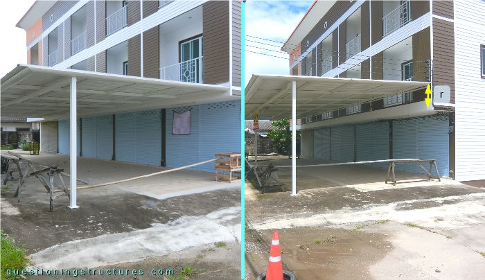
The transverse beam is welded on the top side of the longitudinal beam. Figure 6 shows the canopy roof before and after raising.
| Before raising | After raising |
What is a possible method to raise the above shown canopy roof?