General Information
Figure 1 shows a steel canopy roof of a logistic dock station.
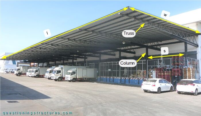
The structure consists mainly of columns, beams, tie beams, trusses, purlins, and metal roofing sheets. The canopy width w ≅ 16 m, the length l ≅ 74 m, and the truss/column spacing s ≅ 6 m. The columns, beams, and tie beams are made of I-sections; the trusses are made of circular hollow sections, and the purlins are made of lipped channels.
Overhang
Figure 2 shows a canopy roof sector.
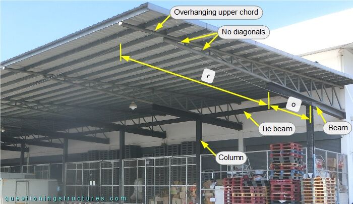
The beams are connected to the RC structure of the building and the top ends of the columns; the overhang o ≅ 4 m. The tie beams are connected to the webs of the beams and are located over the columns.
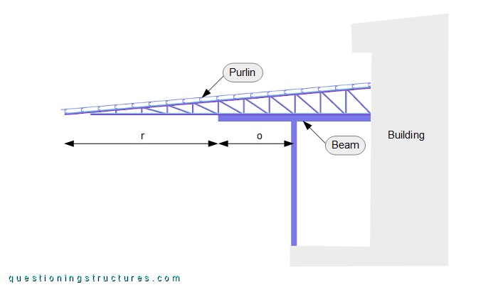
The trusses are connected to the RC structure of the building, and their bottom chords are placed directly over the beams (not attached to them); the overhang r ≅ 8 m. The upper and bottom chords join before the free end (tapered trusses), and the upper chords overhang after it. The diagonals are falling, and the first two fields are without diagonals. The purlins are placed over as well as away from the truss nodes and in the overhang region of the upper chords. Figure 3 shows a schematic lateral view of the structure.
Are the truss members subjected to normal stresses only?
What are other possible canopy structures made of steel that use the columns and the building as supports and probably use fewer resources?
Sag Rods and Roof Cross Bracing
Figure 4 shows a schematic layout of the roof.
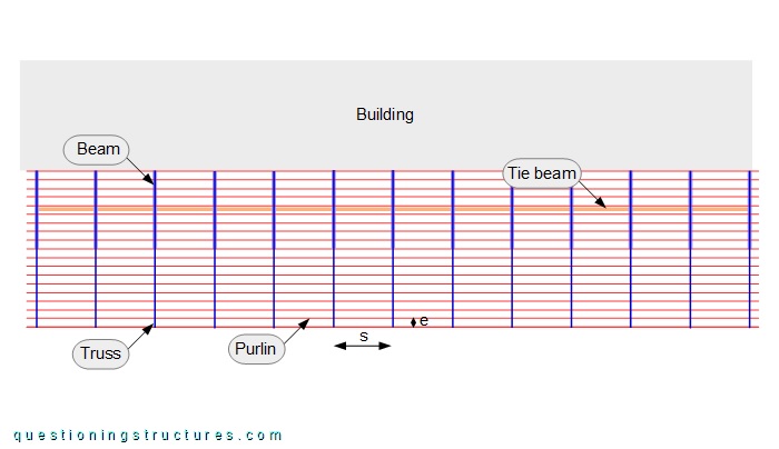
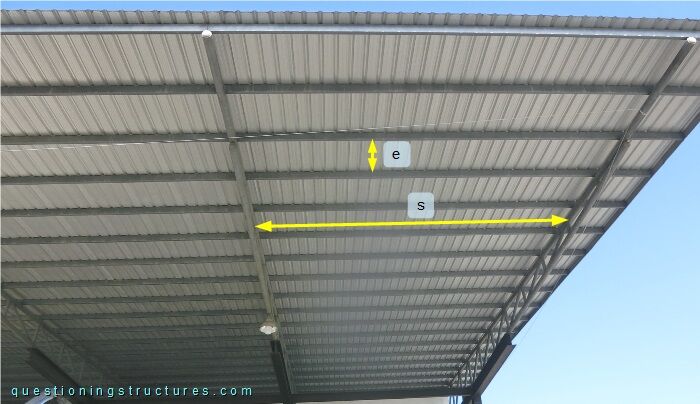
The purlins are continuous over the whole roof length, have a span s ≅ 6 m, a spacing e ≅ 0.9 m, and the roof pitch is about 5 degrees. Figure 5 shows a roof structure sector viewed from below.
When do purlins require sag rods?