General Information
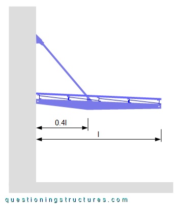
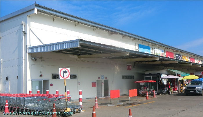
Figure 1 shows a steel canopy roof.
Bending Moment Distribution
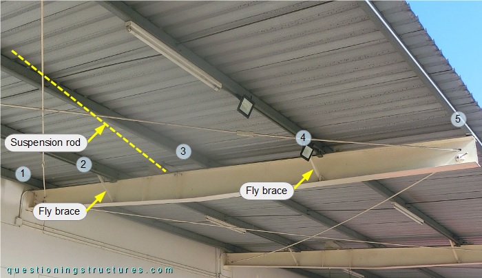
Figure 2 shows a roof structure sector.
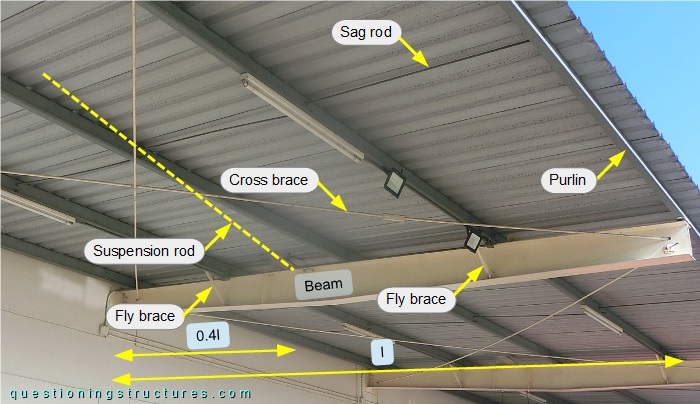
The steel structure consists mainly of beams, suspension rods, purlins, sag rods, fly braces, roof cross braces, and metal roofing sheets. The beams are made of double-tapered I-sections; their length l ≅ 5 m, and the spacing ≅ 4.5 m. The largest cross-section is located at a distance from the building of 0.4l (suspension rod connection). Two fly brace pairs made of L-sections are installed per beam, and the purlins are made of Z-channels.
Figure 3 shows the connection between the beam and the suspension rod.
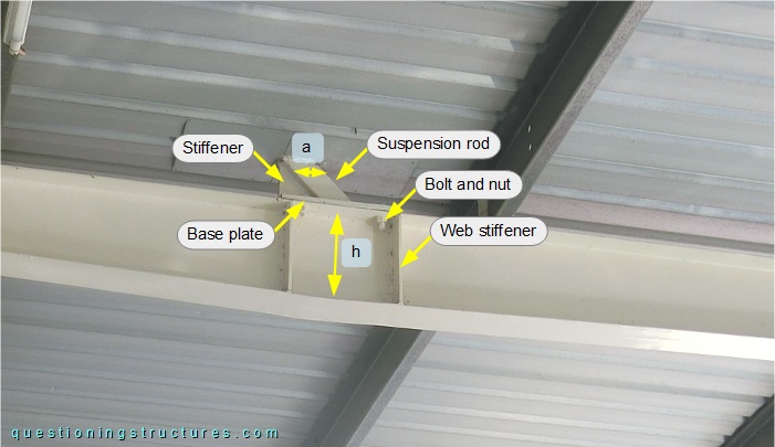
The suspension rod is made of a square hollow section, and the connection to the beam consists of a base plate with a stiffener and four bolts and nuts, which are installed in the four corner regions of the base plate; vertical web stiffeners are installed near the bolts. The ratio between the suspension rod side length (a) and the height (h) of the beam is r = 0.25, and the suspension rod is about 3.5 meters long.
Figure 4 shows two structural models.
| Model 1 | Model 2 |
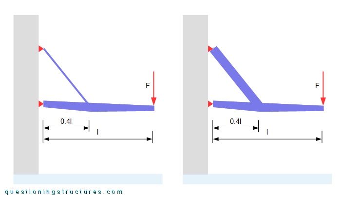
Model 1 is the above shown canopy roof, while model 2 has stiffer suspension rods (same stiffness as the beam's maximal stiffness). The red arrows (F) represent forces placed at the free end of the beams. Assume that the connections between the beams and the suspension rods are of type fixed, and the connections to the building are of type hinged.
What affects the bending moment distribution of the beams and the suspension rods?
Fly Bracing
Figure 5 shows a roof structure sector.
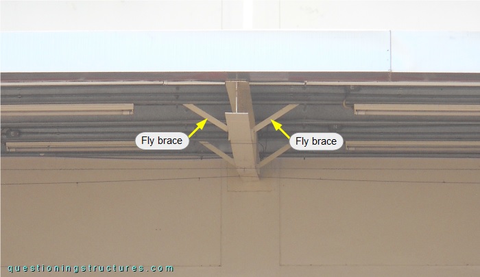
The fly braces are connected to the webs of the beams (bottom region) and the webs of the purlins. Fly braces are not installed under purlin 3 (near the suspension rod connection). Fgure 6 shows a fly-braced beam.
Alternative Variant
Figure 7 shows a schematic lateral view of the canopy roof.