General Information
Figure 1 shows a steel canopy roof.
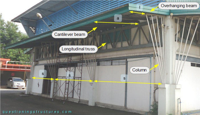
The steel structure consists mainly of a longitudinal truss, four columns, four overhanging beams, cantilever beams, purlins, and metal roofing sheets. The longitudinal truss is made of rectangular hollow sections; the cantilever beams, the overhanging beams, and the purlins are made of lipped channels, while the columns (multi-column bents) are made of circular and square hollow sections. The cantilever arm a ≅ 2.5 m, the overhang l ≅ 1 m, and the columns' spacing s ≅ 5 m.
Cantilever Connection
Figure 2 shows a schematic layout of the structure.
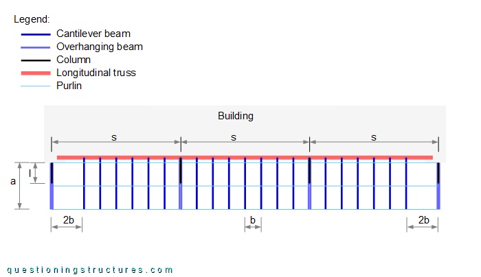
The longitudinal truss has a span of about 3s, and the cantilever beams' spacing is b ≅ 0.6 m and 2b (side spacing). The overhanging beams consist of two side-by-side placed lipped channels. Figure 3 shows a canopy roof sector.
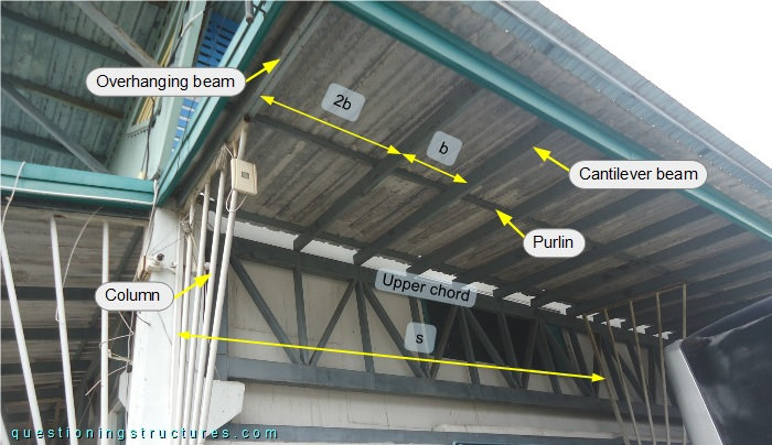
The cantilever beams are connected to the upper chord of the longitudinal truss as shown in figures 4 and 5.
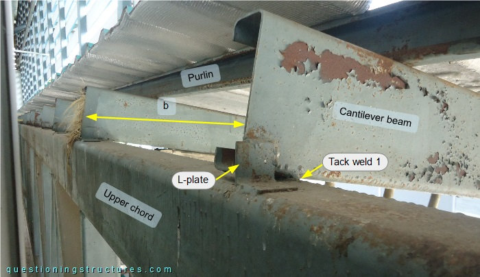
The cantilever beam is connected to the upper chord by a welded L-plate and two tack welds (1 and 2).
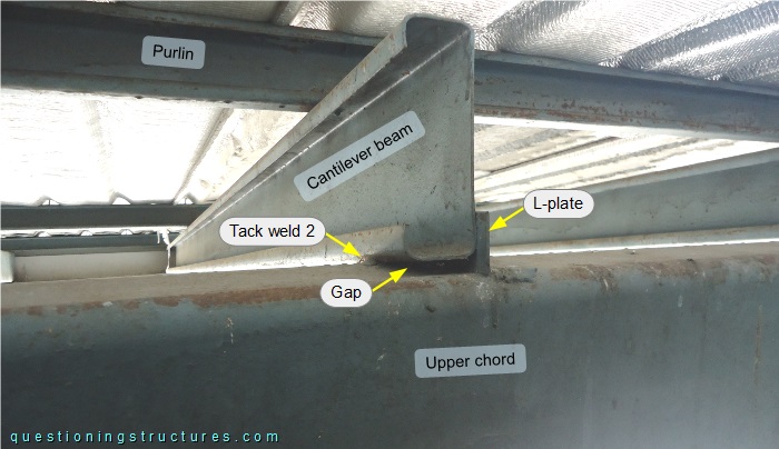
There is a gap between the upper chord and the flange of the cantilever beam.
How are the forces (e.g., bending moments) of the cantilever beams transferred to the longitudinal truss?
Which limit states are probably of particular interest?
Tributary Area
Figure 6 shows a schematic three-dimensional view of the structure.
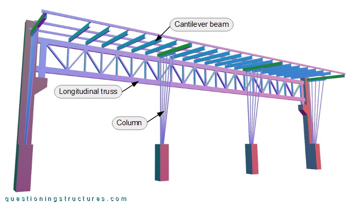
The overhanging beams are shown in red.
Would alternative variants (e.g., without the longitudinal truss) be possible? Would they be more efficient?