General Information
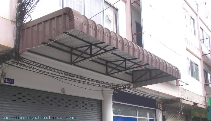
Figure 1 shows a steel canopy roof.
Canopy Roof Failure
Figure 2 shows the canopy roof of figure 1 and a next to failed steel canopy roof.
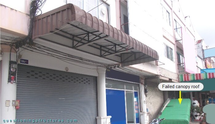
Both canopy roofs have the same cantilever truss type and external roof geometry. Figure 3 shows the failed canopy roof viewed from below.
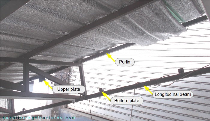
The connection between the canopy roof and the reinforced concrete structure of the building consisted of plates and anchor bolts. The upper plates are connected to the purlin; the bottom plates, to the longitudinal beam. The upper and bottom plates are different in geometry, connection position, and number. Figure 4 shows a schematic front view of the canopy roof to building connection.
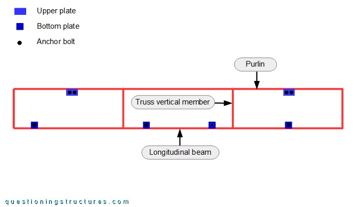
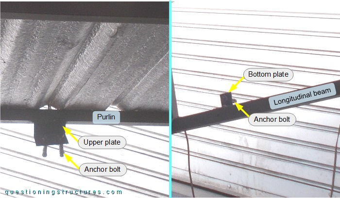
Each upper plate connects two anchor bolts, while each bottom plate connects a single anchor bolt. Figure 5 shows an upper and a bottom plate.
| Upper plate | Bottom plate |