General Information
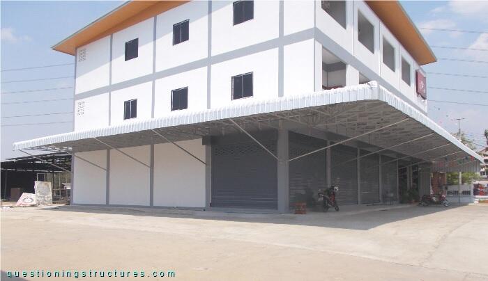
Figure 1 shows a steel canopy roof.
Structural Concept
Figure 2 shows a canopy roof sector viewed from below.
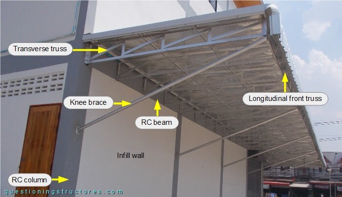
The steel structure consists mainly of transverse trusses, a longitudinal front truss, knee braces, purlins, and metal roofing sheets. The transverse trusses are connected to the RC beam and the longitudinal front truss; the knee braces, to the RC columns and the longitudinal front truss. The knee braces and the longitudinal front truss are connected as shown in figure 3.
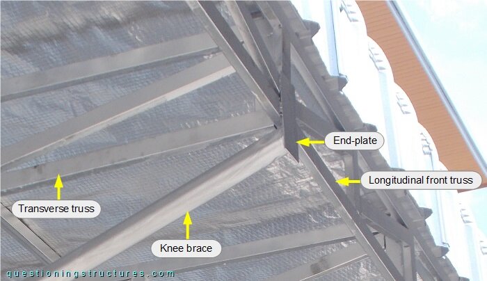
The knee brace and the longitudinal front truss are connected by a welded end-plate, which vertically cantilevers from the longitudinal front truss, and the knee brace is placed in the cantilever region. Figure 4 shows a schematic roof sector layout.
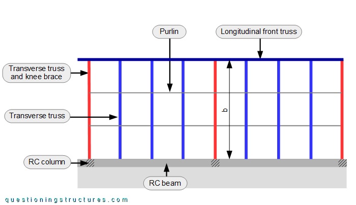
The width b ≅ 3 m.
Knee Braces
Figure 5 shows the knee brace layout.
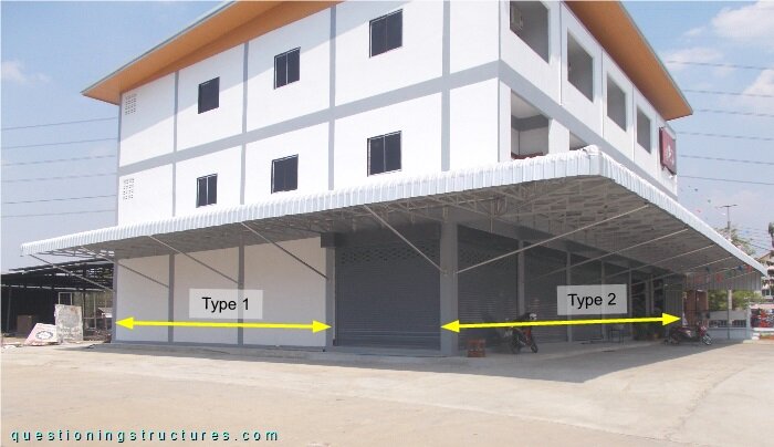
There are two types of knee braces: type 1 consists of a single member, while type 2 consists of two members. Figure 6 shows a knee brace type 2.
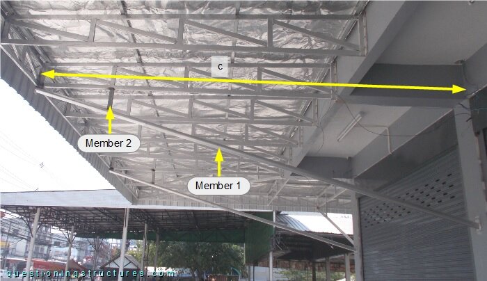
The distance c ≅ 4 m.
Transverse Trusses to Reinforced Concrete Beam Connections
The transverse trusses are connected to the reinforced concrete beam as shown in figure 7.
| Over RC column (knee brace region) | Over infill wall |
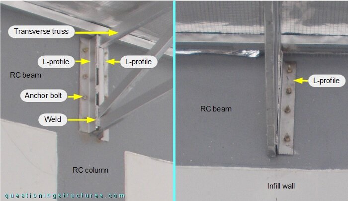
The connection over the RC column has two L-profiles; over the infill wall, a single L-profile. The remaining parts are similar for both connections: welds and anchor bolts.
Corner Zone Trusses
Figure 8 shows the corner zone viewed from below.
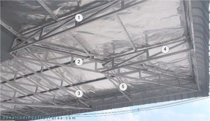
The corner zone has five trusses.