General Information
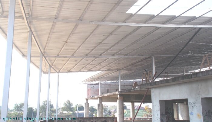
Figure 1 shows the construction site of a commercial building extension.
Beams and Purlins
Figure 2 shows a schematic cross-section of the structure.
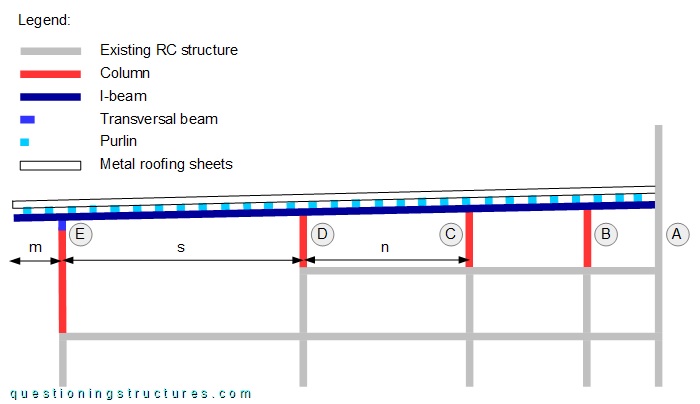
The new steel structure consists mainly of columns, beams, purlins, sag rods, and metal roofing sheets. The continuous I-beam has five supports (A to E); the overhang m ≅ 2.5 m, and the main span s ≅ 12 m. Figures 3 and 4 show the main span (s).
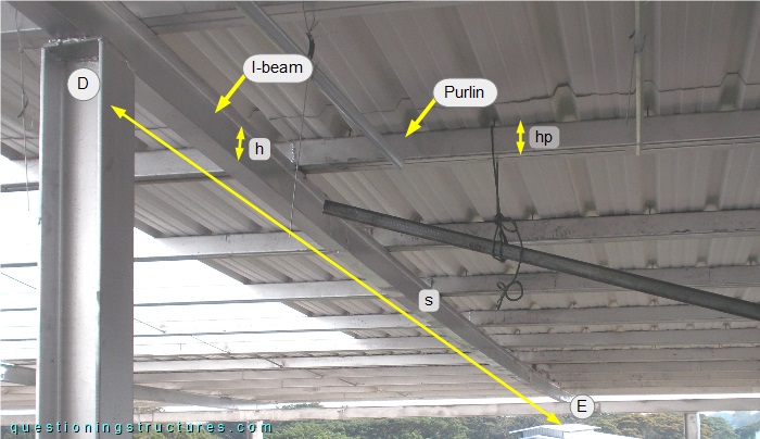
The I-beam height h ≅ 15 cm, and the purlin height hp ≅ 10 cm.
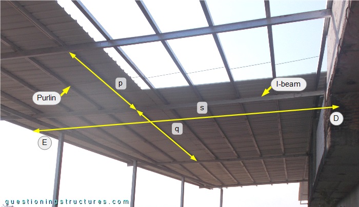
The purlin span p ≅ 5 m, while the purlin span q ≅ 9 m. A purlin consists of a built-up section made of two side-by-side placed rectangular hollow sections that are joined by intermittent welding. Figure 5 shows a roof structure sector, while figure 6 shows a schematic cross-section of the I-beam and the purlin.
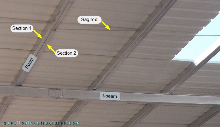
Sag rods are installed between the purlins.

What is the purpose of the installed sag rods?
The finished building extension has a suspended ceiling with gypsum boards, as shown in figure 7.
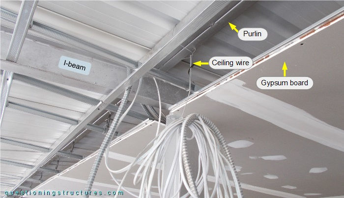
The suspended ceiling is connected to the purlins by steel ceiling wires.
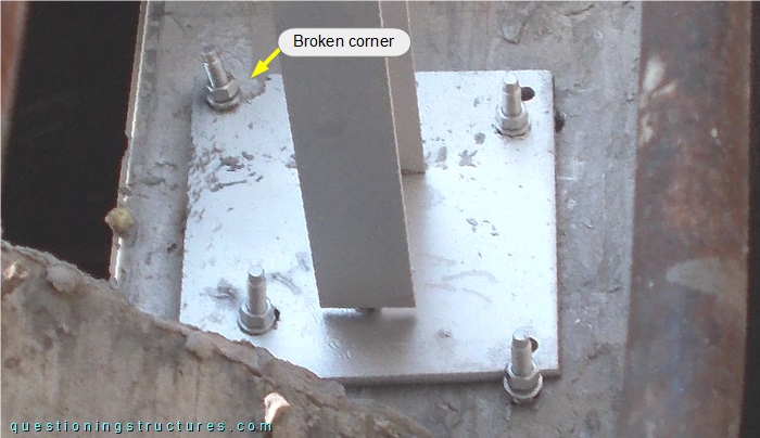
Connection Between I-Beam and RC Column
Figure 8 shows the I-beam between supports A and B, while figures 9 and 10 show the connection to the RC column (support A).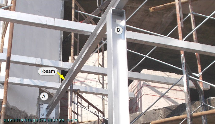
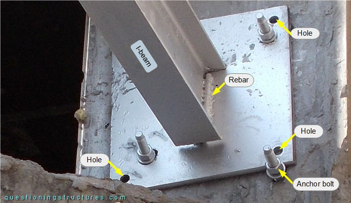
The I-beam is connected to an end plate by a welded rebar, and the end plate is connected to four anchor bolts. The anchor bolt layout is asymmetric, and two of them adjoin the end plate, which has three circular holes and a broken corner.
Metal Roofing Sheets
Figure 11 shows a roof structure sector.
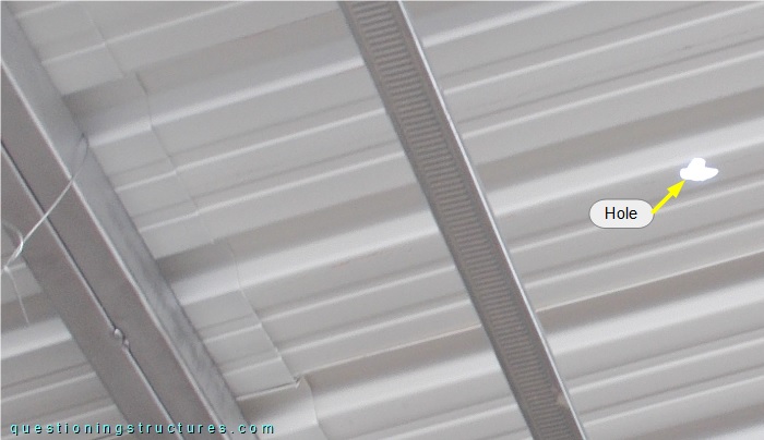
There is a hole in the metal sheet.
What are the main consequences?