General Information
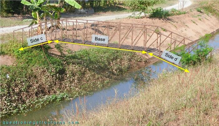
Figure 1 shows a pedestrian frame bridge.
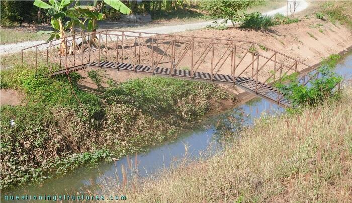
| Main span: | ≅ 6 m |
| Width: | ≅ 0.8 m |
| Girder: | Steel frame |
Structural Behavior
Figure 2 shows the bridge.
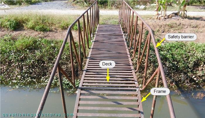
The frame is made of U-sections, the deck of L-sections, and the safety barrier of circular hollow sections. The safety barrier has a truss-like geometry and is connected to the frame as shown in figure 3.
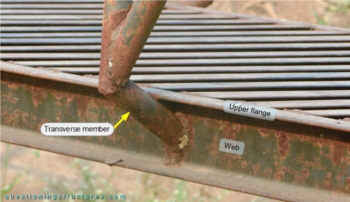
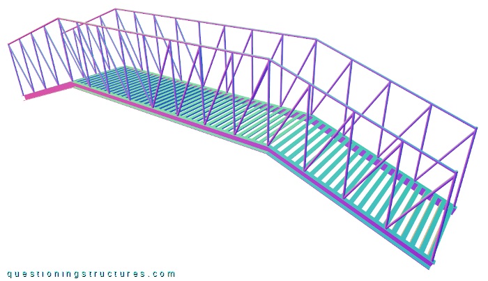
The safety barrier is connected to the web by transverse members (weld connection). Suppose that the safety barrier does not have transverse members and is connected to the upper flange (weld connection), as shown in the schematic three-dimensional view in figure 4.
Structural Model
Figure 5 shows the bridge.
The frame is trapezoidal-shaped. Figure 6 shows three structural models.
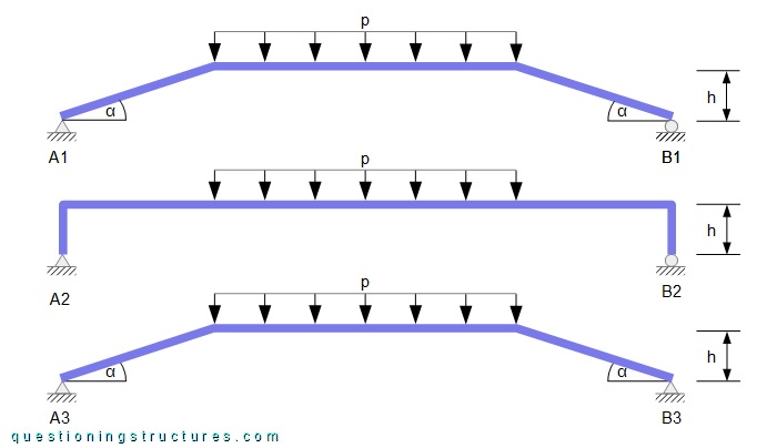
All models have the same constant cross-section, material parameters, span to height (h) ratio, and uniformly distributed load (p). The supports are of type pinned (triangle) and roller (circle).
Which is the structure with the greatest normal force?
Consider the connection between the steel frame (made of U-sections) and the RC abutment. What are some possible constructive details for pinned and roller support types?