General Information
Figure 1 shows a pedestrian frame bridge.
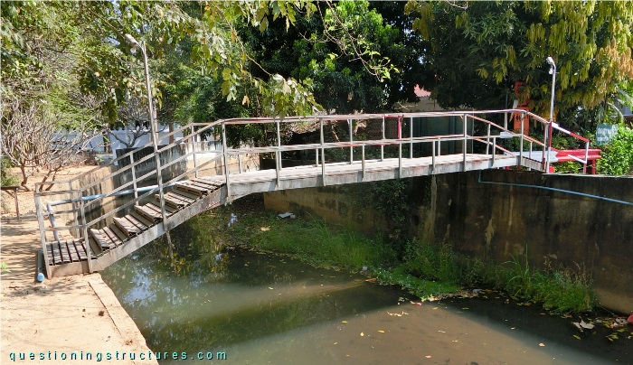
| Main span: | ≅ 8 m |
| Width: | ≅ 1.2 m |
| Girder: | Cold formed steel (CFS) frame |
Cold Formed Steel (CFS)
Figure 2 shows a side view of the bridge.
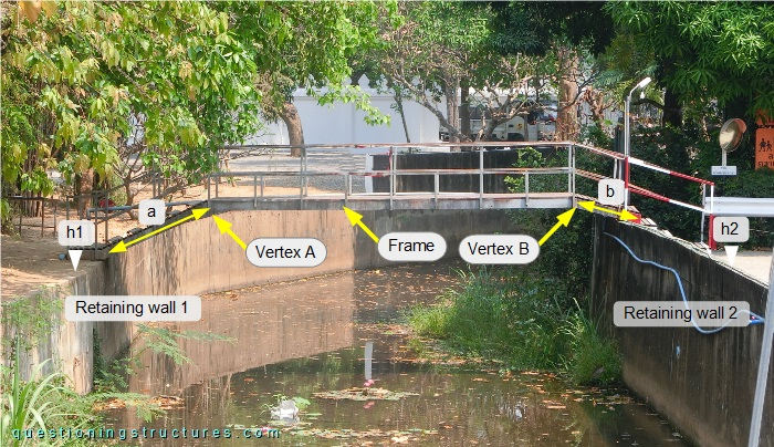
The bridge is supported by two reinforced concrete retaining walls with different crown elevations (h1 < h2). The shape of the frames is trapezoidal asymmetric (a > b); vertex A is haunched, while vertex B is not haunched. Figure 3 shows a bottom view of the bridge.
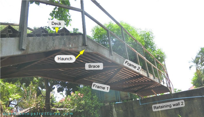
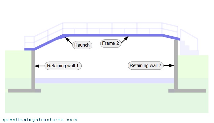
The frames, braces, and the deck are made of lipped channels (CFS). Figure 4 shows a schematic longitudinal section of the bridge.
What are the main pros and cons of using CFS sections instead of HFS sections?
Figure 5 shows the connection to retaining wall 2.
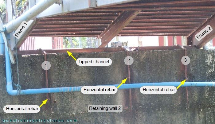
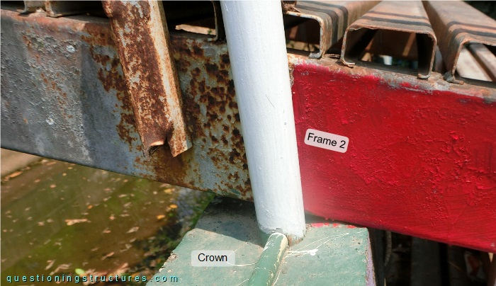
Frame 1 is placed over a lipped channel that lies over the crown, while frame 2 is placed directly over the crown. Over the lipped channel are placed three U-like shaped rebars (1 to 3) that are each connected to a horizontal (through the retaining wall passing) rebar. Frames 1 and 2 have the same cross-section, and the crown is even. Frames 1 and 2 to retaining wall 2 connections are shown in figures 6 and 7, respectively.
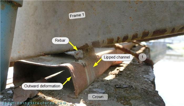
A short rebar is welded over a flange; the lipped channel is deformed.
Assume that the frames' connections to retaining wall 1 are of type pinned. Is contraflexure in frames 1 and 2 activated?