General Information
Figure 1 shows a hybrid cable-stayed suspension bridge that is used by motorcycles, bicycles and pedestrians.
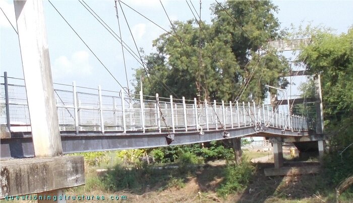
| Type | Single-span hybrid cable-stayed suspension bridge |
| Main span | ≅ 75 m |
| Deck width | ≅ 2 m |
| Girder | Steel twin I-girder |
| Pylon | Reinforced concrete (A-type, longitudinal) |
| Stay cable arrangement | Radial (two cable planes) |
Arrangement of Stay and Hanger Cables
Figure 2 shows a schematic three-dimensional view of the main span.
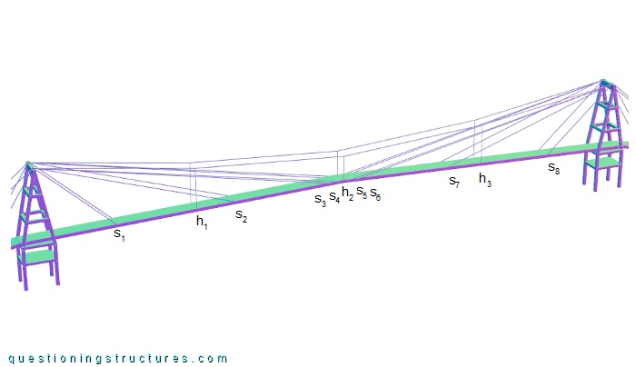
The girder is connected to 6 hanger- and 16 stay cables. The former have an approximately constant spacing (s), while the latter have a non-linear decreasing spacing toward the mid-span region. Figure 3 shows a side view of the mid-span region.
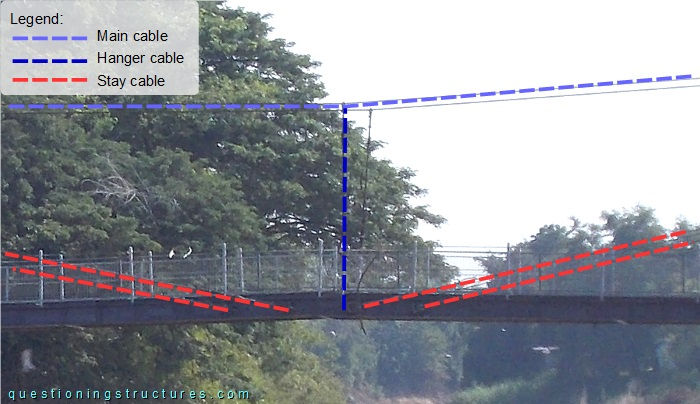
Eight stay cables and two hanger cables are installed in the mid-span region; the distance a ≅ 3 m.
Stay Cable Vibration
Figure 4 shows a schematic lateral view of the bridge.
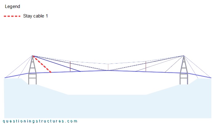
Video 1 shows stay cable 1 during hand-induced vibration.