General Information
Figure 1 shows a pedestrian hybrid cable-stayed suspension bridge.
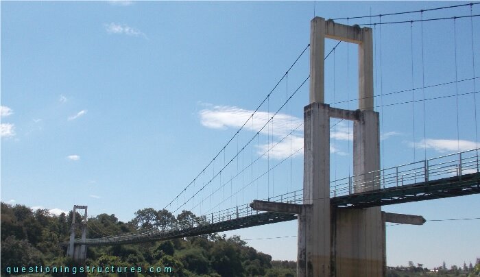
| Type | Three-span hybrid cable-stayed suspension bridge |
| Main span | ≅ 140 m |
| Deck width | ≅ 2 m |
| Pylon | Reinforced concrete with two cantilever lateral beams |
| Girder | Steel truss |
| Stay cable arrangement | Single (two cable planes) |
Arrangement of Stay and Lateral Cables
Figure 2 shows a schematic three-dimensional view of a bridge sector on one shore.
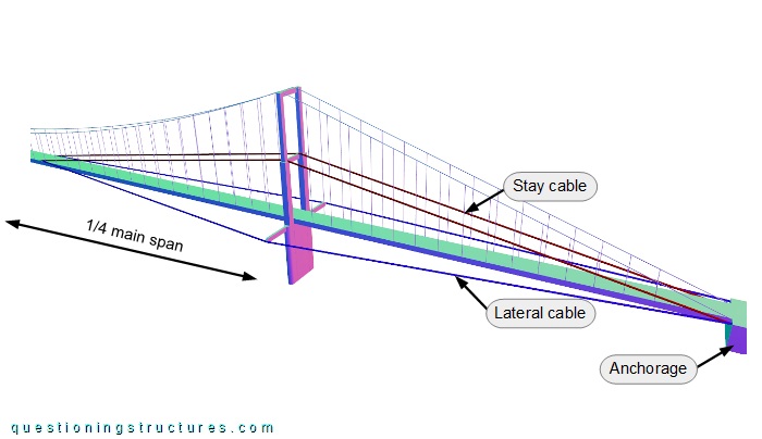
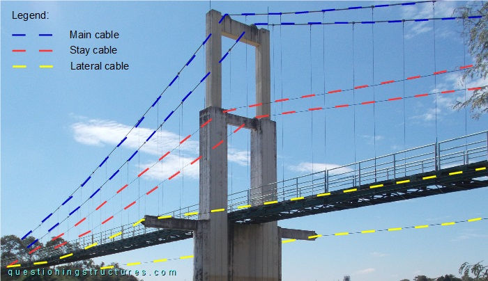
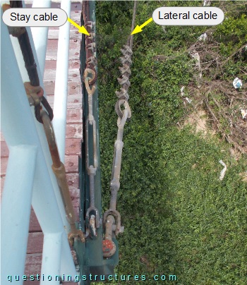
The bridge has two stay and two lateral cables per shore. They are connected to the anchorages, the pylons, and the main span girder. The stay cables are connected to the pylons' mid-height cross-beams, while the lateral cables are connected to the pylons' cantilever lateral beams. The stay and lateral cables are connected to the main span girder at approximately a quarter of the main span. Figure 3 shows a side view of a pylon, while figure 4 shows a girder connection.
Truss Girder
Figure 5 shows a schematic cross-section of the bridge.
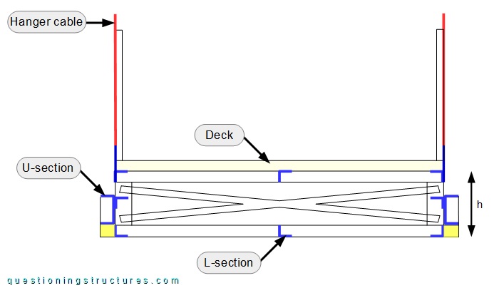
The truss is made of L- and U-sections; the latter are located on the two longitudinal sides and are connected to the bottom chords by short cantilevered L-sections. The height h ≅ 0.4 m. Figure 6 shows a side view of the truss.
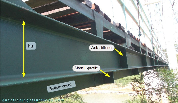
Vertical web stiffeners are installed on the U-sections, and the height hu ≅ 0.2 m.
Truss Girder Deflection
Figure 7 shows the bridge viewed from the deck.
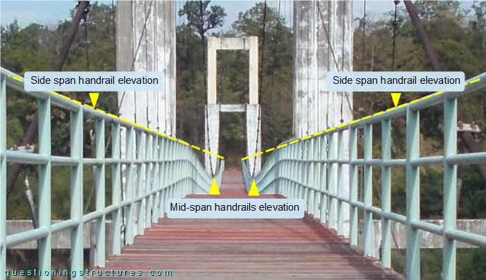
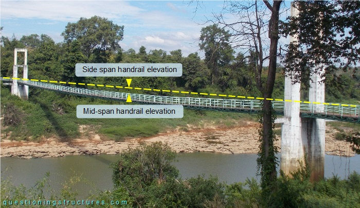
The main span truss is deflected, as noticeable by the elevation difference between the side- and mid-span handrails. Figure 8 shows a side view of the main span.
What are the main structural consequences?