General Information
Figure 1 shows a hybrid cable-stayed suspension bridge that is used by motorcycles, bicycles and pedestrians.
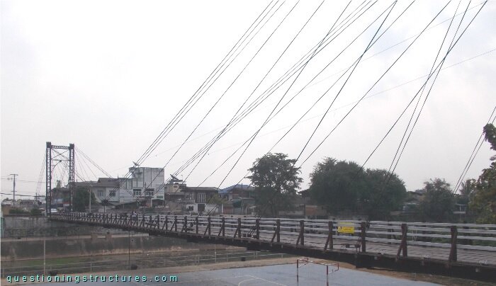
| Main span: | ≅ 80 m |
| Deck width: | ≅ 4 m |
| Pylon: | Steel trusses |
| Girder: | Steel transverse beam |
| Stay cable arrangement: | Radial (two cable planes) |
Suspension System
Figure 2 shows a schematic lateral view of the bridge.
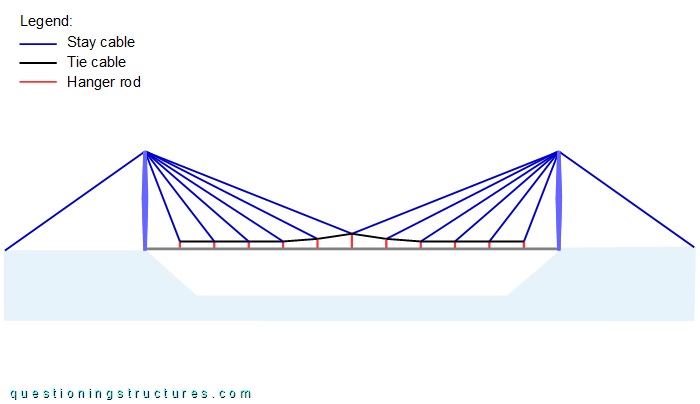
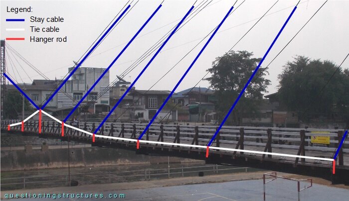
The suspension system consists of stay cables, tie cables, and hanger rods. Figure 3 shows a side view of a main span sector.
The load path of the suspension system is shown in figure 4.
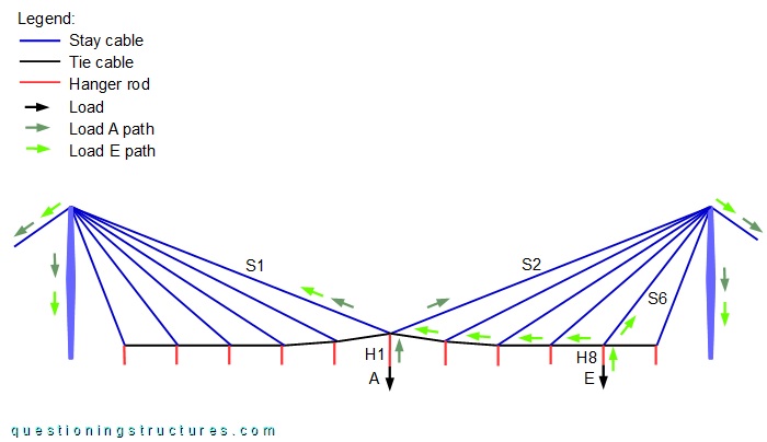
The mid-span stay cables S1 and/or S2 are always used as a load path. Load A is transferred to the the pylons and anchorages by hanger rod H1 and stay cables S1 and S2; load E is transferred by hanger rod H8, stay cable S6, four tie cables, and stay cable S1. Figure 5 shows the bridge in the mid-span region.
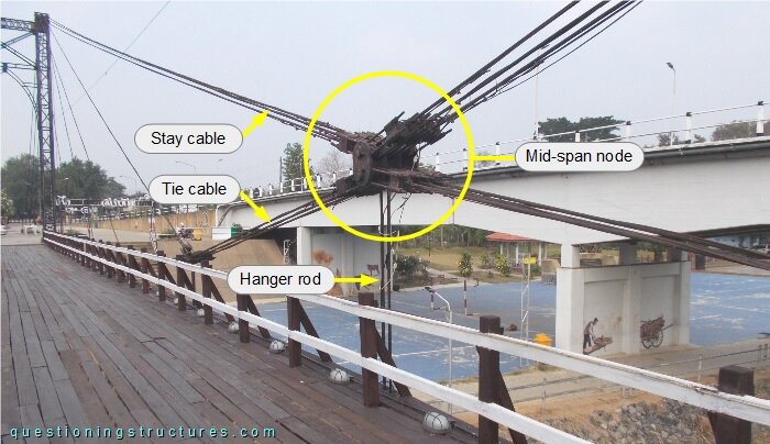
The mid-span node is shown in figure 6.
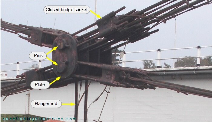
The end fittings of the stay and tie cables consist of closed bridge sockets, and the hanger rods are U-shaped. The node consists of four plates and two pins. The remaining nodes are arranged as shown in figure 7.
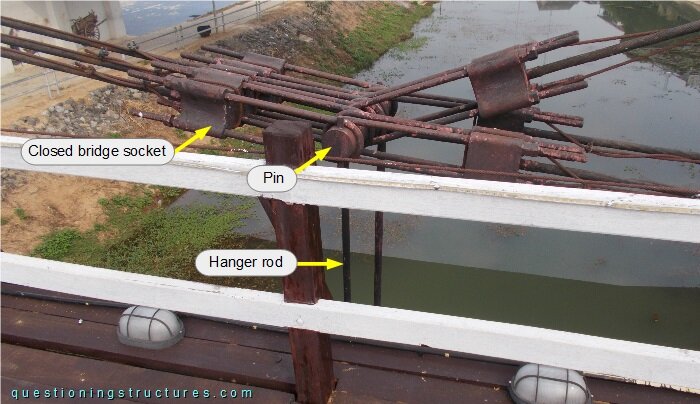
The node consists of a single pin.