General Information
Figure 1 shows a freestanding carport.
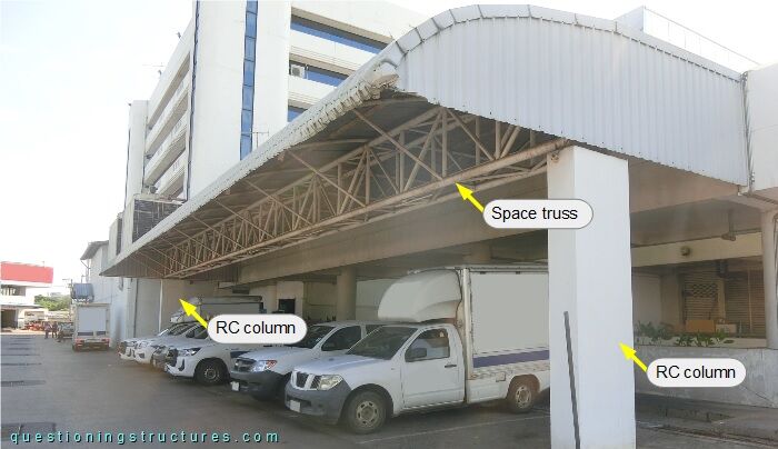
The structure consists mainly of two reinforced concrete columns, a space truss, braces, transverse beams, purlins, and metal roofing sheets.
Space Truss
Figure 2 shows a schematic layout of the carport.
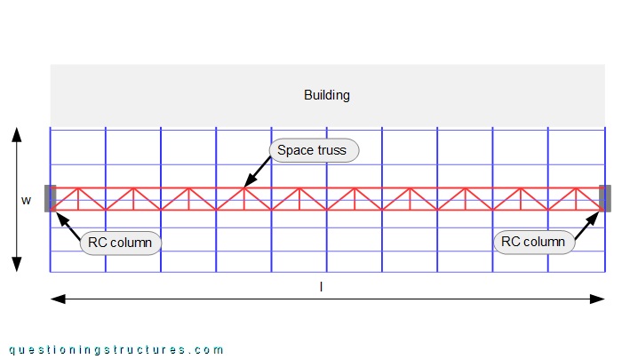
The carport length l ≅ 25 m, and the width w ≅ 6.5 m. The RC columns are installed at mid-width (w/2); they support the space truss and have a size of about 0.5 x 1.2 m. Figure 3 shows a roof sector.
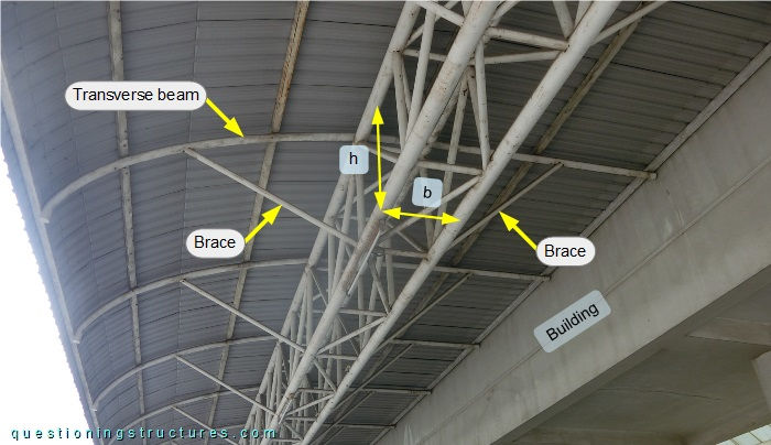
The space truss is made of circular hollow sections and has a rectangular cross-section; the width b ≅ 0.8 m, and the height h ≅ 1.6 m. Zigzag diagonals, verticals/cross members are equally installed on the four space truss sides.
The transverse beams have a curved (front) and a straight (back) sector; each of them is connected to two upper chords and two braces; the latter are connected to the bottom chords. The carport and the building are not structurally connected. Figure 4 shows a schematic cross-section of the carport, while figure 5 shows a variant with a triangular space truss.

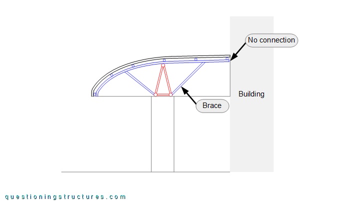
The triangular space truss has the same width, height, and web member arrangement as the rectangular space truss.
Would a 2D-truss variant be possible with the same roof (no building connection) and column configuration?