General Information
Figure 1 shows a freestanding steel bikeport.
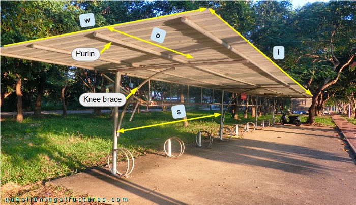
The steel structure consists mainly of columns, curved knee braces, transverse (overhanging) beams, a tie truss without diagonals, purlins, and metal roofing sheets. All structural members (except for the sheets) are made of circular hollow sections. The roof length l ≅ 17.5 m, the width w ≅ 3 m, and the column spacing s ≅ 4.5 m. The purlins overhang on both sides; the overhang o ≅ 2 m.
Purlins/Roof Vibration
Figure 2 shows the bikeport.
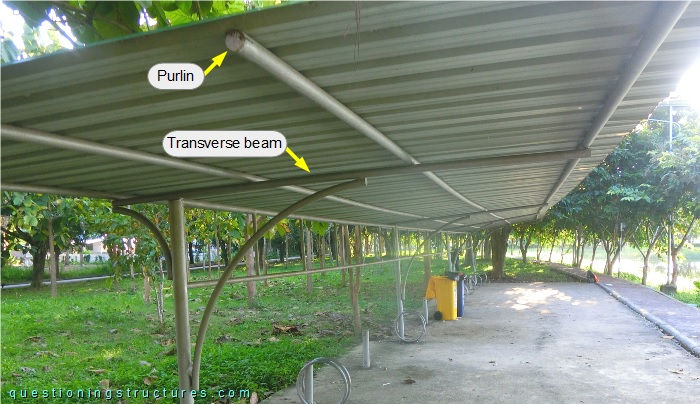
The purlins are continuous over the whole roof length and have a diameter of about 4 cm; that gives a main span-to-depth ratio of about 113. The sheets are connected to the purlins by sheet metal screws, while the purlins are connected to the transverse beams by welding, as shown in figure 3.
| Sheet to purlin | Purlin to transverse beam |
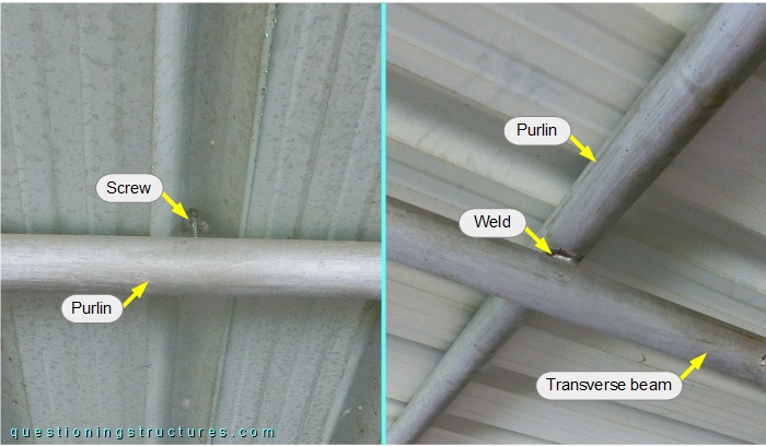
Figure 4 shows a schematic layout of the bikeport.
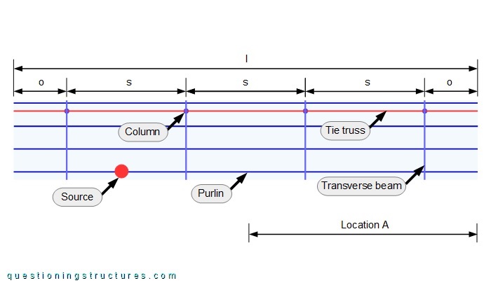
Video 1 shows the purlins/roof vibration during hand-induced excitation of location A; the vibration source location is marked by the red circle.
The maximal amplitude at s/2 (yellow asterisk) is about 6 cm.
Can the wind cause a bigger amplitude?
Is a structural failure due to purlins vibration induced by wind possible?