General Information
Figure 1 shows an attached carport.
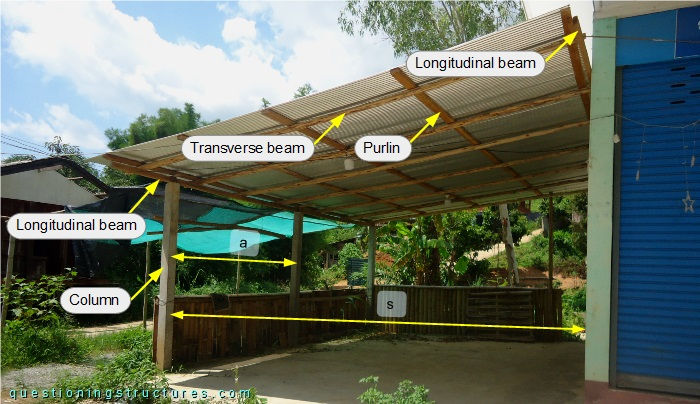
The structure consists mainly of three columns, longitudinal and transverse beams, purlins, and corrugated zinc roofing sheets. The columns are made of reinforced concrete, the longitudinal beams and the purlins are made of timber (rectangular sections), and the transverse beams are made of peeled logs. The span s ≅ 4.5 m, and the columns' spacing a ≅ 2.5 m.
Structural Connections
Figure 2 shows the roof structure.
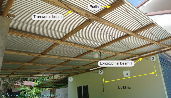
The zinc sheets are nailed (umbrella head nails) over the purlins, the purlins are nailed over the transverse beams, and the transverse beams are notched at the ends and nailed over the longitudinal beams; the connection to the building consists of three anchor bolts (1 to 3) with a spacing of approximately a (columns' spacing). Figure 3 shows anchor bolt 3 region.
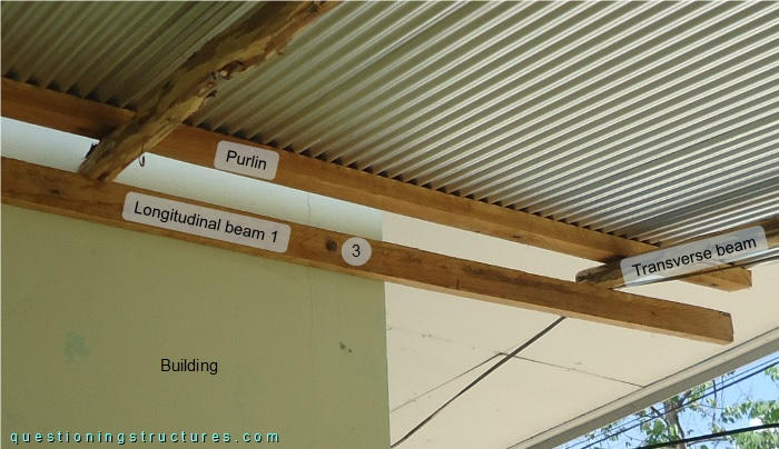
The longitudinal beam and the building are in direct contact (no gap) over the entire building length. Figure 4 shows the connection between the longitudinal beam and the column.
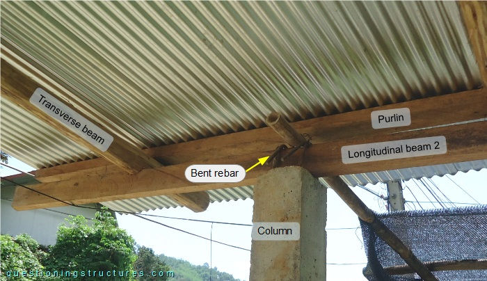
The longitudinal beam is placed over the column and fastened with its four (protruding) rebars, which are bent over the longitudinal beam. A schematic lateral view of longitudinal beams 1 and 2 is shown in figure 5.
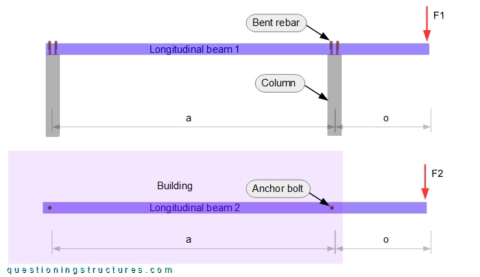
Both beams have the same cross-section, mechanical properties, and distances between the supports; the red arrows (F1 and F2) represent vertical forces placed at the free ends of the overhangs (o).
Is the failure mode of both beams the same?
What are other possible structural connections? How do those connections affect the beams' behavior?
Materials
Figure 6 shows a schematic three-dimensional view of the carport.
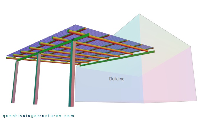
Consider the reinforced concrete columns, the timber roof structure, and the zinc roofing sheets.