General Information
Figure 1 shows a covered parking for construction vehicles.
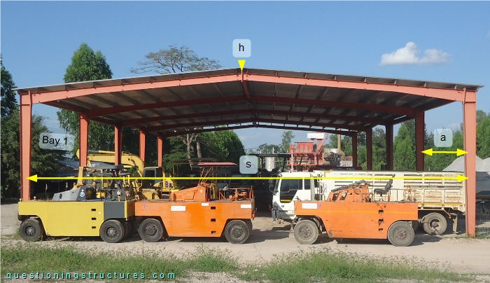
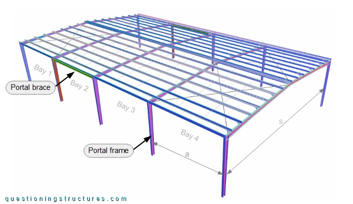
The steel structure consists mainly of portal frames, portal braces, eaves beams, purlins, fly braces, sag rods, struts, roof cross braces, and metal roofing sheets. There are four bays; the portal frames are made of I-sections, their span s ≅ 20 m, the spacing a ≅ 8.5 m, and the apex elevation h ≅ 7 m. Figure 2 shows a schematic three-dimensional view of the structure.
Roof Cross Bracing and Vertical Bracing
Figure 3 shows a schematic layout of the structure.
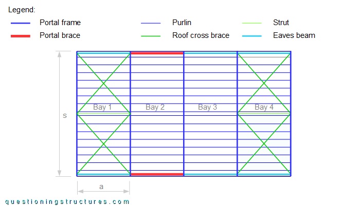
Roof cross braces are installed on the side bays (1 and 4), while portal braces (vertical bracing) are installed on bay 2. Figure 4 shows a sector of bays 1 and 2.
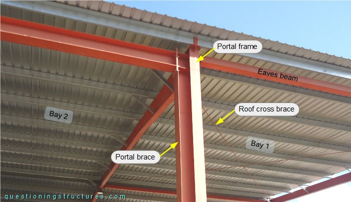
Figure 5 shows a schematic layout of the structure and five variants.
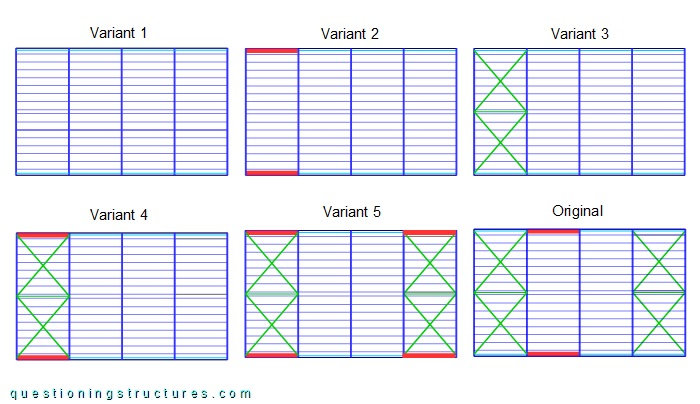
Variant 1 does not have roof cross and portal braces; portal braces only are installed on variant 2; roof cross braces only are installed on variant 3; variant 4 has a single external bay braced (portal braces and roof cross braces); and variant 5 has two external bays braced.
Portal Bracing
Figure 6 shows a front view of bay 2.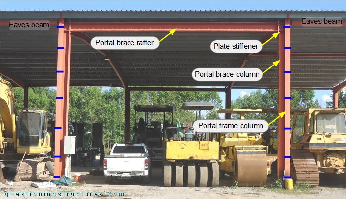
The portal braces are made of H-sections of the same size, and plate stiffeners are installed in the corners. The flanges of the portal brace columns are connected to the webs of the portal frame columns by bolt pairs; the blue lines indicate the approximate bolts' locations. Figure 7 shows a base region.
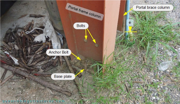
The two portals have one common base that consists of a base plate and four anchor bolts (2x2). The portal brace columns are shorter than the portal frame columns; the starting point of the portal brace column is indicated by the elevation (e).
What about the lateral stiffness increase due to the above shown portal braces compared (e.g.) with vertical cross braces?
Single-Side Fly Bracing
Figure 8 shows a roof sector.
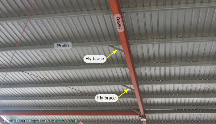
The fly braces are installed on one side of the rafters; they are connected by bolts (to the purlins) and bolted gusset plates (to the rafters). The purlins are made of Z-channels, and the fly braces are made of lipped channels.
When are two-side fly braces required?