General Information
Figure 1 shows an attached carport.
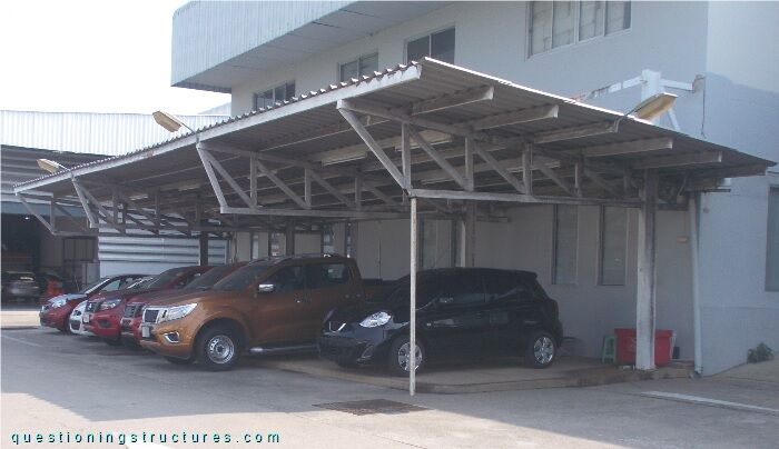
The structure consists mainly of columns, trusses, suspension rods, purlins, roof cross braces, and asbestos roofing sheets.
Structural Concept
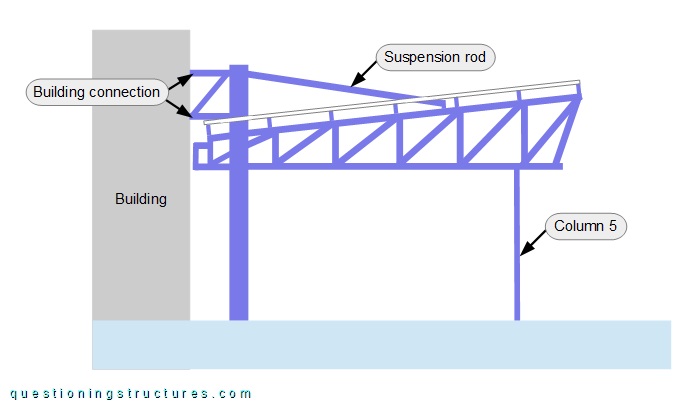
Figure 2 shows a schematic layout of the structure.
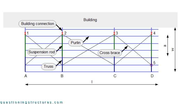
The length l ≅ 18 m, and the width w ≅ 5.5 m. There are five columns and four trusses. The back columns (1 to 4) are made of I-sections, while the front column (5) is made of a circular hollow section and connected to truss D. The back columns are structurally connected to the building, and each truss is also connected to a suspension rod; the connection is located at a distance from the back column of a ≅ 0.5w. Roof cross braces are installed between the trusses.
Figure 3 shows a lateral view of the carport.
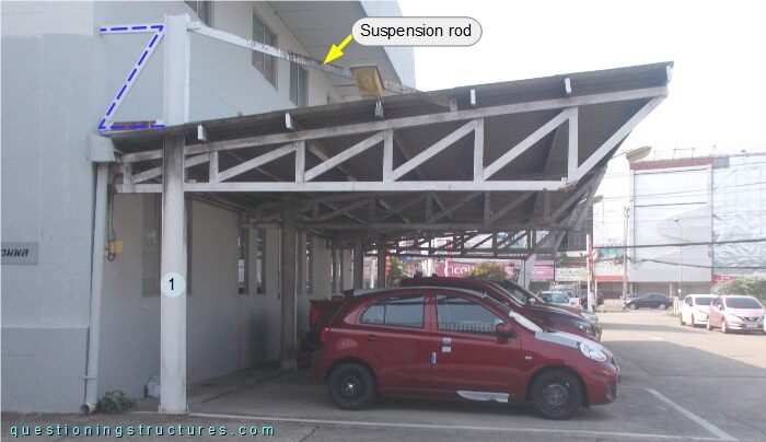
The trusses are made of square and rectangular hollow sections and are tapered toward the back columns. Figure 4 shows two cantilever tapered trusses.
| Truss A | Truss A1 |
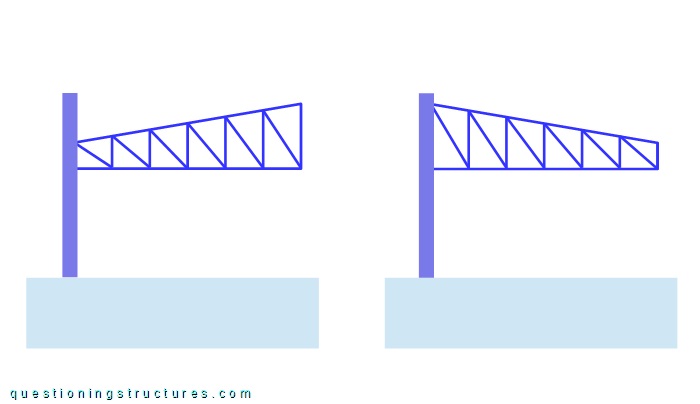
Cantilever truss A is tapered toward the column, while cantilever truss A1 is tapered toward the free end.
Figure 5 shows a schematic lateral view of the carport.
What are some possible reasons to connect the carport to the building?
Three (out of four) building connections failed; figure 6 shows a failed connection.
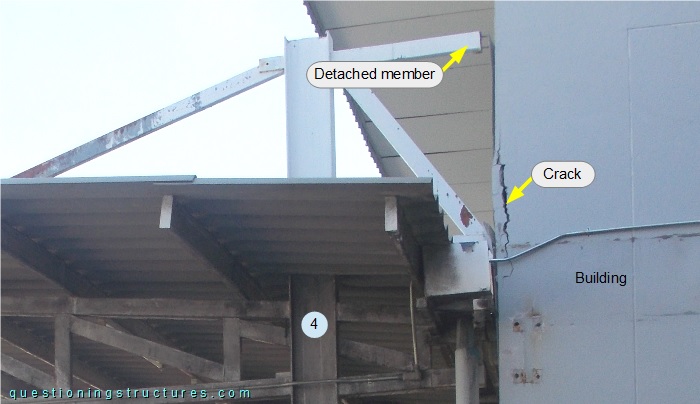
A detached member and a vertical crack in the RC structure of the building are noticeable.
Does the carport have a structural safety or serviceability problem without column 5?