General Information
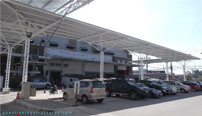
Figure 1 shows a freestanding steel carport.
Carport Functions
Figure 2 shows a front view of a carport sector.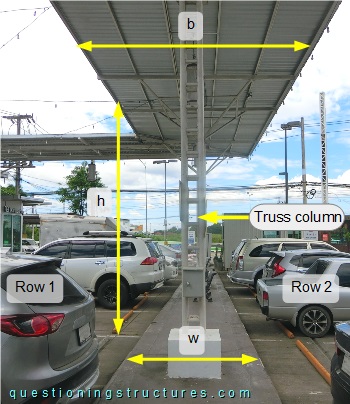 The roof has an elevation of about 6 m above the ground, and its width b ≅ 5 m. The truss columns are placed at mid-width and in the middle of the walkway, which has a width w ≅ 1.5 m. The distance between the walkway's ends and the wheel stops e ≅ 0.6 m.
How does a rainfall with wind affect the sheltered surface?
Roof Structure
Figure 3 shows a roof sector.
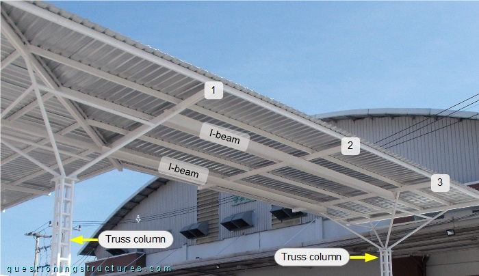
The shown roof sector is supported by two truss columns with an inverted pyramid structure installed on their top ends. The roof structure consists of two longitudinal I-beams, three transverse beams (1 to 3), purlins, and metal roofing sheets. The I-beam span s ≅ 6 m. Transverse beam 2 is placed over the two I-beams, which are connected to transverse beams 1 and 3 as shown in figure 4.
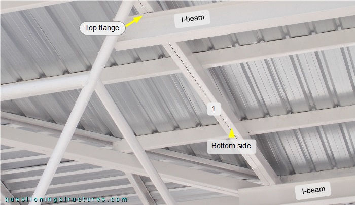
The top flanges of the I-beams are welded directly to the bottom side of transverse beam 1, which is made (like transverse beams 2 and 3) of two side-by-side placed rectangular hollow sections.
What are the main structural and/or constructive phase problems?