General Information
Figure 1 shows a freestanding steel carport.
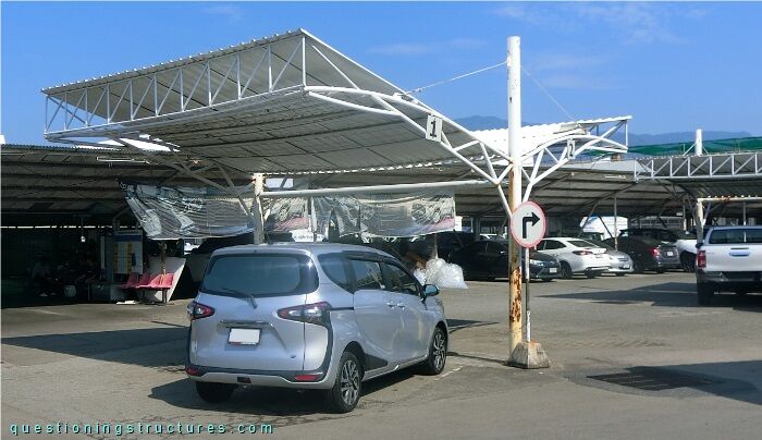
The carport is made of two equal roof units. The steel structure consists mainly of two columns, transverse- and longitudinal trusses, a tie beam, roof cross-braces, stay cables, purlins, an anti-bird net structure, and metal roofing sheets. The columns, trusses, purlins, tie beam, and the beams for the anti-bird net support are made of circular hollow sections, while the stay cables and roof cross-braces are made of steel wire ropes.
Carport Structure
Figure 2 shows the carport.
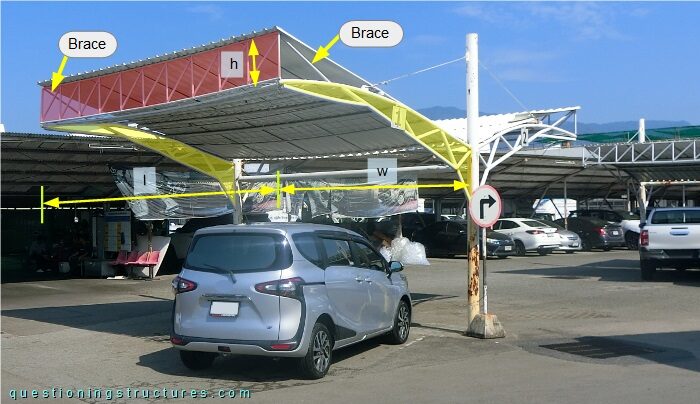
The length l ≅ 5 m, and the width w/2 ≅ 4 m. The longitudinal truss (red background) is installed over the free ends of the two transverse trusses (yellow background) and braced by two diagonals connected to the upper chords; the longitudinal truss height h ≅ 0.5 m. Figure 3 shows a lateral view of the carport.
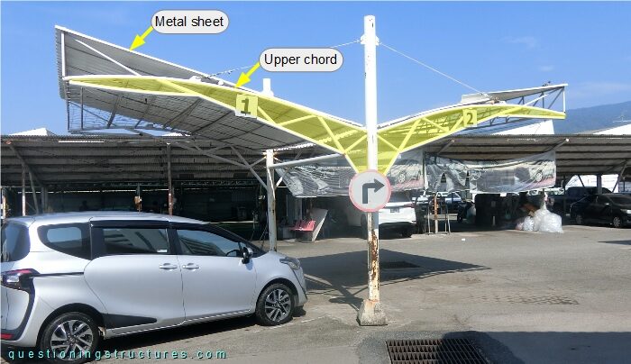
The transverse trusses are approximately tapered toward the free ends; the upper chords are curved, while the metal sheets have a constant slope. Figure 4 shows a roof unit.
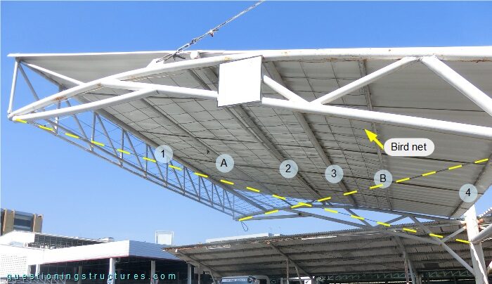
There are four metal sheet supports (1 to 4) with a non-constant spacing. Support 1 is the longitudinal truss, while supports 2 to 4 are the purlins, which are installed over (stacked) and between the upper chords. A and B are the beams for the anti-bird net support, while the yellow dashed lines mark the roof cross-braces, which are connected to the columns as shown in figure 5.
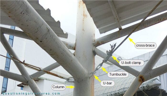
The connection consists of a turnbuckle and a U-bar, which is welded to the column; the wire rope termination consists of a U-bolt clamp. The stay cables are connected to the transverse trusses as shown in figure 6.
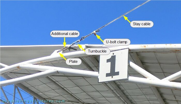
The connection consists of a turnbuckle, an additional cable, and a single-hole plate welded to the upper chord (away from a truss node); each cable is terminated with a U-bolt clamp. Figure 7 shows a schematic three-dimensional view of the used carport and an alternative variant.
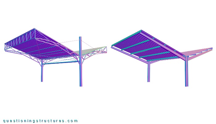
The steel structure of the alternative variant consists mainly of two Y-frames, purlins, and metal roofing sheets. The Y-frames are made of I-sections (standard and tapered), while the purlins are made of lipped channels. Both variants have the same external geometry.
For the used carport. Are all elements required for structural reasons?
What are some possible reasons to choose the used carport instead of the alternative variant?