General Information
Figure 1 shows an abandoned construction site of a residential building.
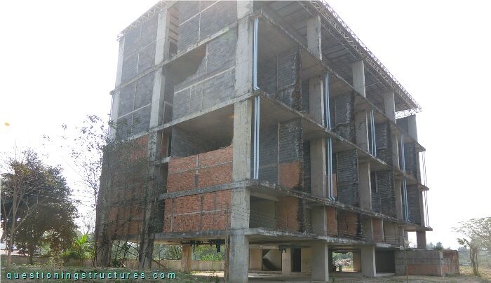
| Building width | ≅ 19 m |
| Building length | ≅ 40 m |
| Building height | ≅ 22 m |
| Plane shape | U-asymmetrical |
| Main structure | RC columns and prestressed concrete flat slabs with slab bands |
| Roof structure | Steel trusses, beams, purlins, and metal roofing sheets |
| Non-load bearing elements | All masonry walls |
Seismic Safety
Figure 2 shows a schematic layout of the ground floor.
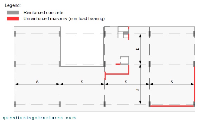
The span s ≅ 10 m, a ≅ 9 m, and b ≅ 7 m. The columns, two stair walls, and the elevator core are the continuous vertical elements made of reinforced concrete. The size of a RC column is about 0.4 m x 1.2 m, and the elevator core has a size of about 1.5 m x 1.5 m. The post-tensioned flat slabs have a thickness of about 0.25 m, and the slab bands have a thickness of about 0.15 m. Figure 3 shows a schematic three-dimensional front view of the building.
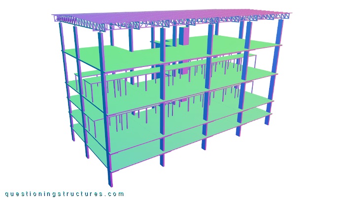
The floor heights are not constant. The ground and the first floors have a height of about 2.5 m, and the two floors above have a double-height ceiling with a height of about 5 m, which is also the height of the last (roof) floor. Figure 4 shows a schematic three-dimensional back view of the building.
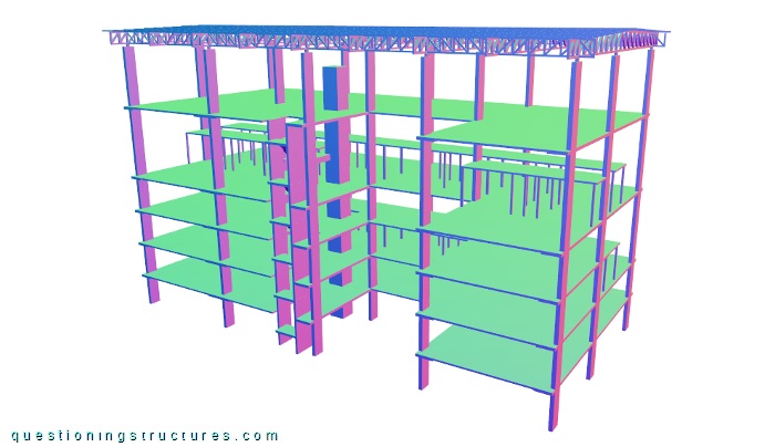
The back floor arrangement differs from the front floor arrangement: there is only one floor with a double-height ceiling, which is the floor under the roof floor; the ground floor until the third floor are 2.5 m height floors. Figure 5 shows a double-height ceiling floor.
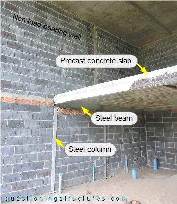
The intermediate slabs are made of precast concrete elements that are supported by a steel structure made of columns and beams. The unreinforced non-load bearing walls are made of a single wythe of hollow concrete bricks with a width of about 7 cm.
Which additional data is required to make a more accurate evaluation of the building's seismic safety?
Non-Load Bearing Masonry Wall Cracks
Figure 6 shows a schematic layout of floor 3.
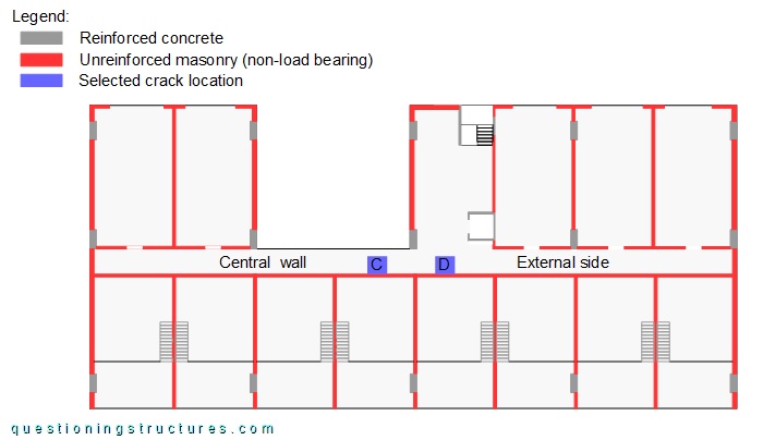
The central wall is made of a single wythe of hollow concrete bricks. The cracks are located along the entire wall and are vertically oriented. Two crack locations (C and D) are shown in figures 7 and 8, respectively.
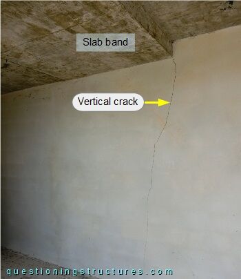
Crack C is located under the slab band edge and runs over the entire wall height; the crack is wider on the top of the wall, and becomes less wide on the bottom of the wall.
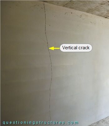
Crack D runs over the entire wall height with a similar opening geometry as crack C. The top of the central wall viewed from the internal (not yet plastered) side is shown in figure 9.
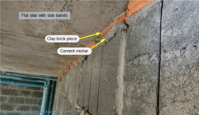
The gap between the last course of the wall and the flat slab with band slabs is filled with clay brick pieces and cement mortar. Figure 10 shows the used hollow concrete brick.
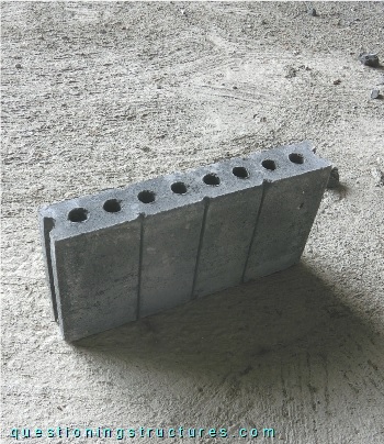
The width ≅ 7 cm, the height ≅ 19 cm, and the length ≅ 39 cm.