General Information
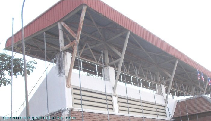
Figure 1 shows a covered tribune.
Structural Concept
Figure 2 shows a schematic lateral view of the structure.
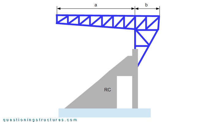
The girder consists of a cantilever truss that is connected at the top and at the rear of the reinforced concrete structure. The cantilever arm a ≅ 6 m, and the back span b ≅ 1.5 m. Figure 3 shows a further variant.
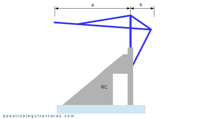
The girder consists of a braced overhanging beam. The reinforced concrete structure connections are placed at the same locations as the used variant.
What are some possible reasons to choose the used variant instead of variant A?
Cantilever Trusses
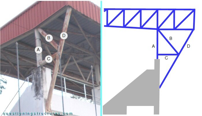
Figure 4 shows a side view of the back span region and a schematic lateral view of it.
Cantilever Trusses to RC Structure Connection
Figure 5 shows D-members of the back span.
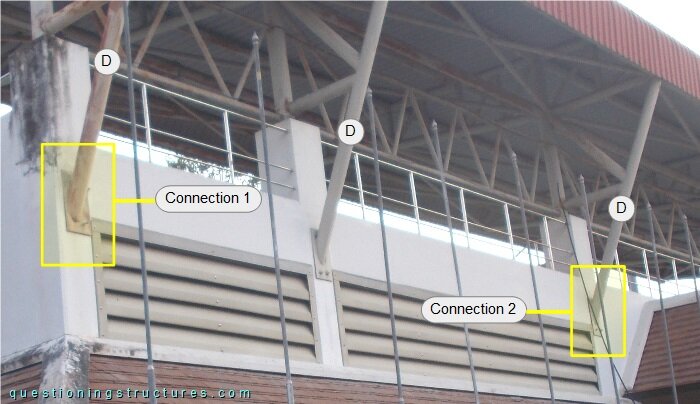
Connections 1 and 2 are shown in figures 6 and 7, respectively.
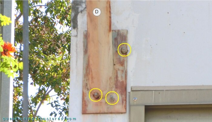
The connection consists of an end-plate and three anchor bolts (marked by the yellow circles).
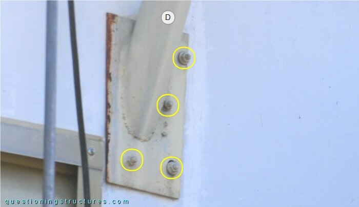
The connection consists of an end-plate and four anchor bolts.
What are the main problems of the above shown connections?