General Information
Figure 1 shows a covered grandstand.
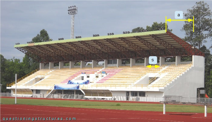
The steel structure consists mainly of cantilever trusses, tie trusses, purlins, roof cross braces, and metal roofing sheets. The trusses are made of rectangular hollow sections, while the purlins are made of lipped channels. The cantilever arm a ≅ 8.5 m, and the spacing s ≅ 4 m.
Connection Between Truss and RC Column
Figure 2 shows a schematic lateral view of the main structure.
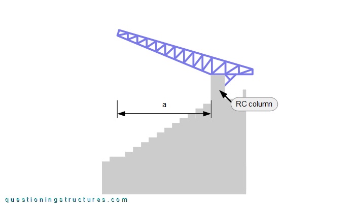
The cantilever truss has a back span and is tapered toward the free ends. Figure 3 shows a lateral view of the connection between the truss and the RC column.
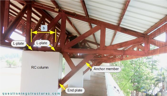
The bottom chord is connected to the top end of the RC column by four L-shaped plates (two per side) and three anchor bolts per L-plate. The anchor member is connected to the bottom chord by welding and to the RC column by an end plate and four anchor bolts. The distance b ≅ 0.7 m, which is the horizontal longitudinal distance between the L-plates. Figure 4 shows the top end region of the RC column.
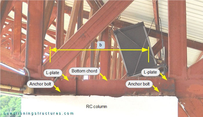
Figure 5 shows a schematic lateral view of the main structure and the connection between the truss and the RC column.
| Main structure | Truss to RC column connection |
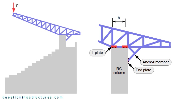
The red arrow (F) represents a force acting at the free end of the cantilever truss.
Figure 6 shows two connections between the truss and the RC column.
| Connection 1 | Connection 2 |
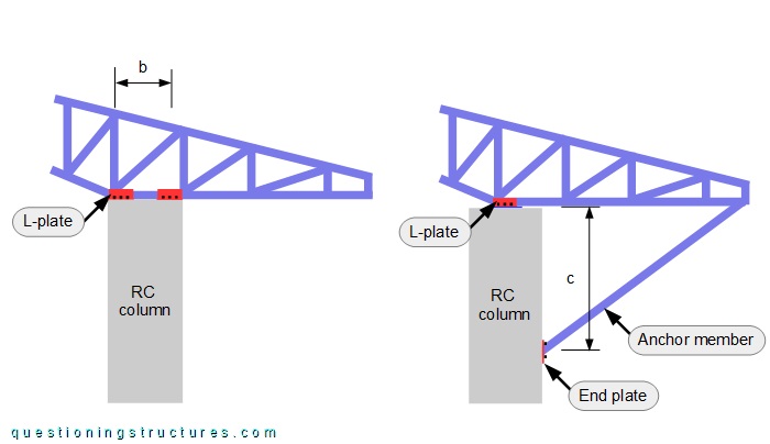
Connection 1 is the used connection without the anchor member. On connection 2 the bottom chord is connected to the top end of the RC column by two L-plates (one per side), and the anchor member is connected at the end of the back span and a lower location to the RC column; the distance c ≅ 2 m, and the number of anchor bolts per L-plate and end plate is unchanged.
What are the structural reasons to choose the used connection?
Roof Cross Bracing
Figure 7 shows a schematic layout of the roof.
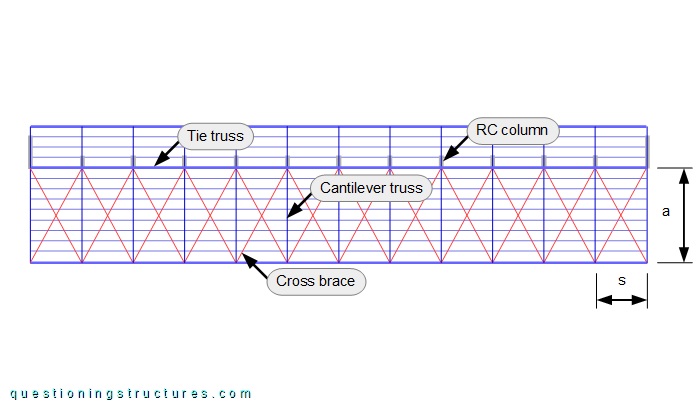
Roof cross braces are installed along the entire roof length.
When is roof cross bracing over the entire roof length required?
Figure 8 shows a roof sector viewed from below.
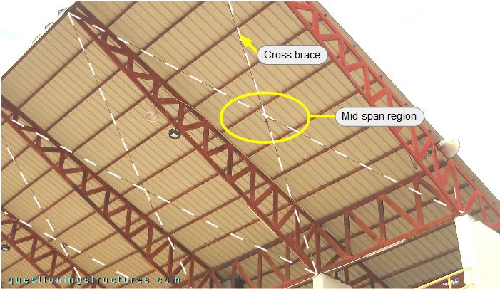
The roof cross braces are made of rods and are directly connected to the bottom chords of the trusses by welding. The rods are tensioned with turnbuckles installed in the mid-span region, as shown in figure 9.
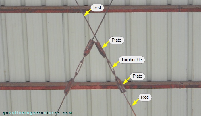
The rods are connected to the turnbuckles' eye and hooked ends by plates (weld connection).
Do the twenty-four installed turnbuckles need to be re-tightened over time?
How is it possible to reach the turnbuckles?