General Information
Figure 1 shows the construction site of a covered grandstand.
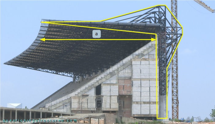
The steel structure consists mainly of trusses, braces, purlins, and metal roofing sheets. The roof width w ≅ 30 m, and the length l ≅ 150 m.
Roof Bracing
Figure 2 shows a schematic lateral view of the main steel structure.
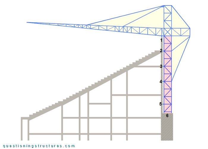
The main steel structure consists of a truss column and a front-braced tapered truss with an anchored back span. The connections to the RC structure are indicated by the numbers, and the truss spacing is about 10 m. Figure 3 shows a roof sector viewed from below.
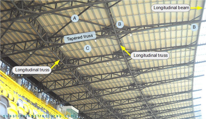
The tapered trusses are connected to the purlins, two longitudinal trusses, a longitudinal beam, and three types of plan braces (A, B, and C). Figure 4 shows a schematic layout of the roof structure.
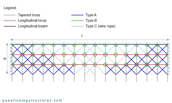
Plan braces are installed over the entire roof. Types A and B are made of circular hollow sections, while type C is made of steel wire ropes. Type A consists of cross members, type B consists of short diagonal-parallel members, and type C consists of cross and diagonal members. Figure 5 shows plan braces types A and B.

Plan braces type A (cross members) intersect directly (section-to-section connection). Plan braces type B that are connected to the longitudinal trusses are installed on two elevation levels (upper and bottom chords), while those connected to the longitudinal beam are installed on one elevation level. Figure 6 shows plan braces type C.
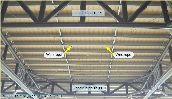
The wire ropes are tensioned with turnbuckles installed on the ropes' ends, as shown in figure 7.
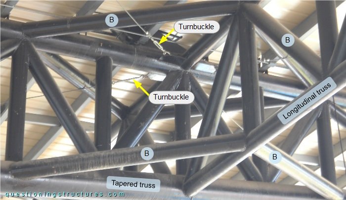
The turnbuckles are of open-body type with hooked and eye ends; the wire rope termination consists of a single U-bolt clamp.
When are longitudinal roof trusses structurelly required?
What are the structural reasons for the above shown roof bracing concept?