General Information
Figure 1 shows a covered sports tribune.
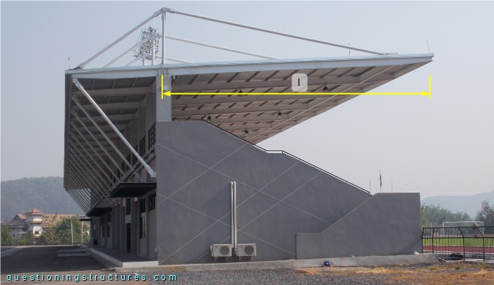
The steel roof structure consists of braced overhanging beams, tie beams, purlins, and metal roofing sheets. The braced overhang l ≅ 13 m, and the spacing ≅ 4 m.
Structural Behavior
Figure 2 shows the covered tribune.
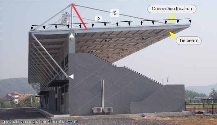
The suspender is marked by the letter S, and the two white triangles mark the pinned support locations of the roof structure. Suppose a suspender arrangement between the actual position and the red line, and consider the uniformly distributed load (p).
What are some possible reasons to connect the suspender near the free-end region?
The back diagonal D is marked in figure 3.
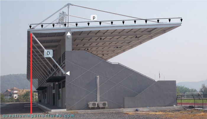
Suppose a back diagonal arrangement between the actual position and the red line (vertical arrangement), and consider the uniformly distributed load (p).
Would placing the back diagonal in a vertical position (external foundation required) be more efficient than connecting the diagonal to the RC structure?
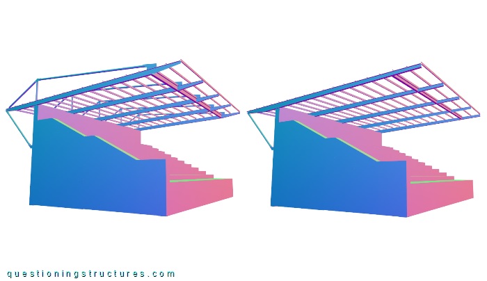
Alternative Variant
A schematic three-dimensional view of the used variant and a variant with a tapered overhanging beam without the suspender brace unit are shown in figure 4.