General Information
Figure 1 shows a covered sports court.
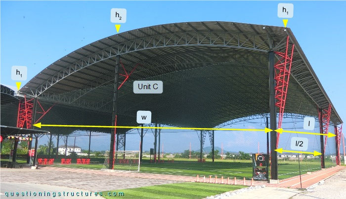
The width w ≅ 33 m, the length l ≅ 55 m, the roof elevation h1 ≅ 11 m, and h2 ≅ 14 m. The steel structure consists mainly of columns, trusses, knee braces, cross braces, purlins, sag rods, and metal roofing sheets. The court is made of three equal units (A, B, and C).
Cross Bracing
Figure 2 shows a schematic layout of the structure.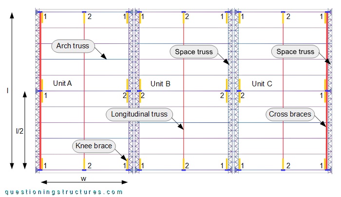
There are two types of columns (labeled with 1 and 2) and three types of roof trusses (arch, space, and longitudinal). The columns are made of I-sections; type 1 has a triangular space truss installed on its external flange, while type 2 has web stiffeners. The roof space trusses have a triangular cross-section. Cross and knee bracing are installed parallel to the l-side; knee bracing (orange lines) on all columns, while cross bracing (red lines) between columns type 1 on the two external l-sides. Figure 3 shows a schematic three-dimensional view of unit C.
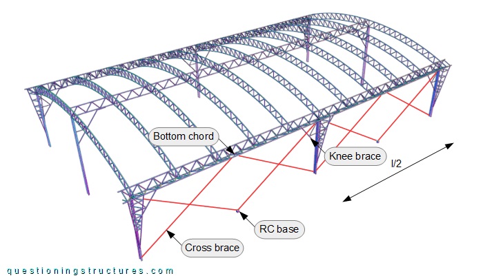
Between two columns are installed four cross braces (two X-members) made of steel wire ropes; they are connected to the bases of the columns, the bottom chord of the roof space truss, and an RC base. Figure 4 shows the l-side of unit C.
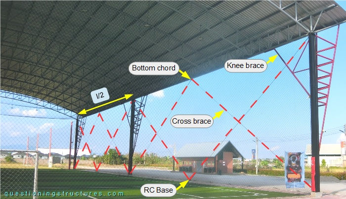
Each cross brace has a length of about 30 meters and a diameter of about 2 centimeters. The connection to the RC base and the connection to the bottom chord are shown in figures 5 and 6, respectively.
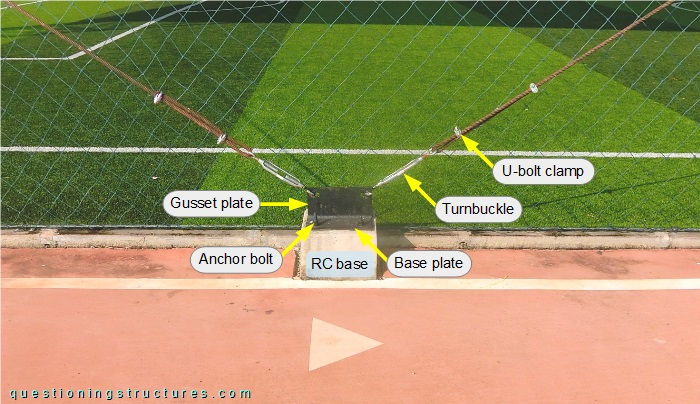
The cross braces are connected to the RC base by open body turnbuckles (eye and hooked ends), a gusset plate, a base plate, and four anchor bolts; the wire rope termination consist of U-bolt clamps.
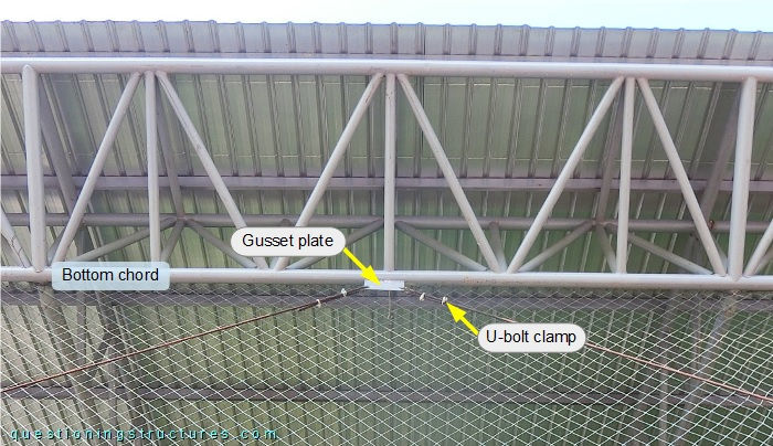
The connection consists of a gusset plate.
Does a turnbuckle structurally behave like a wire rope when subjected to gradually increasing axial loading?
Figure 7 shows a schematic lateral view of the l-side of unit C without knee braces.
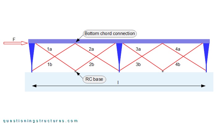
The red lines represent the cross braces (1a to 4b), while the red arrow represents a horizontal force (F) acting on the bottom chord of the roof space truss. Assume that all cross braces are taut and have the same initial tension.
How does the force (F) affect the roof space truss in the indicated bottom chord connection?
Figure 8 shows a schematic lateral view of the l-side of unit C with cross and knee braces.
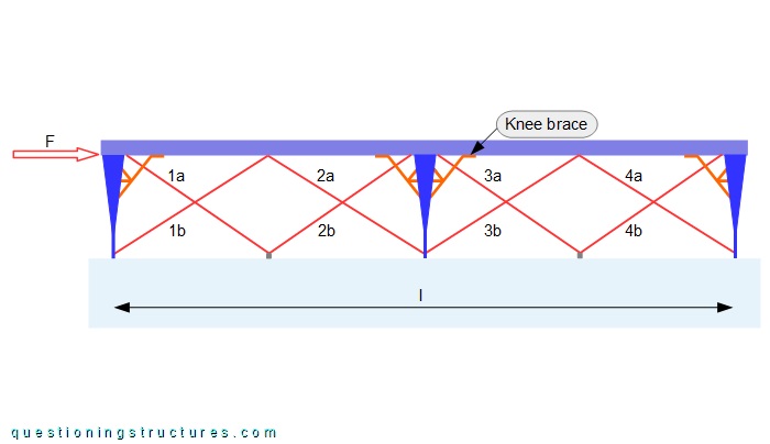
A knee brace is made of three members made of circular hollow sections: an oblique angle, a diagonal, and a horizontal. The oblique angle is connected to the web of the column and the bottom chord of the roof space truss.
How does the lateral bracing system behave when subjected to seismic loading?
How efficient is the lateral bracing concept?