General Information
Figure 1 shows a suspended bridge.
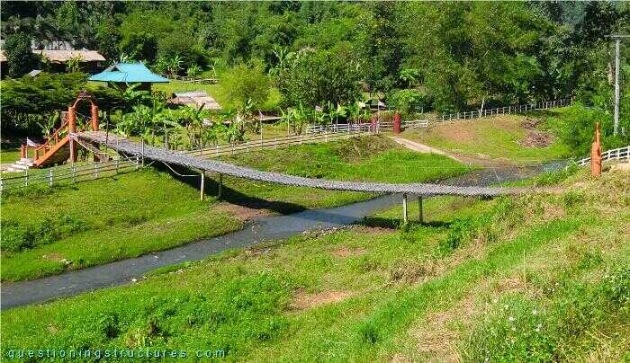
| Tower-to-tower distance | ≅ 35 m |
| Width | ≅ 1.5 m |
| Tower | Timber and reinforced concrete |
| Girder | Timber transverse beam |
| Number of walkway cables | 3 |
Intermediate Supports
Figure 2 shows a side view of the bridge.
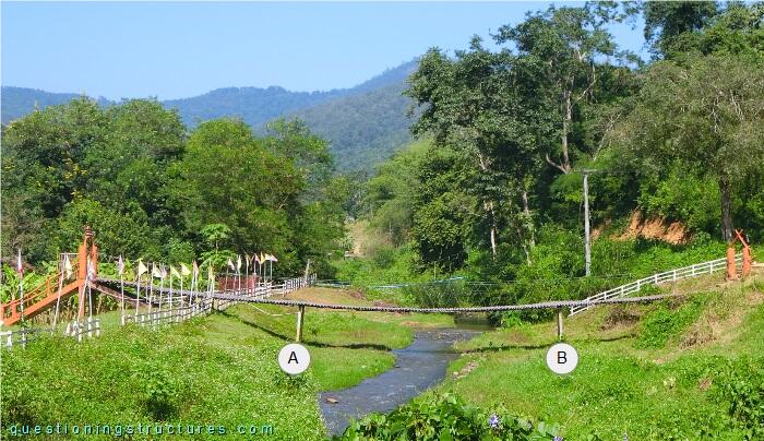
There are two intermediate supports (A and B). Figure 3 shows intermediate support B.
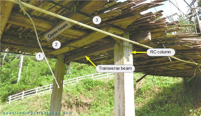
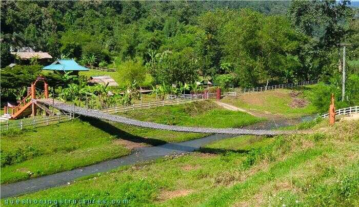
The intermediate support consists of two reinforced concrete columns and a cross-beam made of timber that is connected to the columns by bolts and nuts. The walkway cables are marked by the white dashed lines. Figure 4 shows the bridge without intermediate supports.
Inclined Hangers
Figure 5 shows a deck sector.
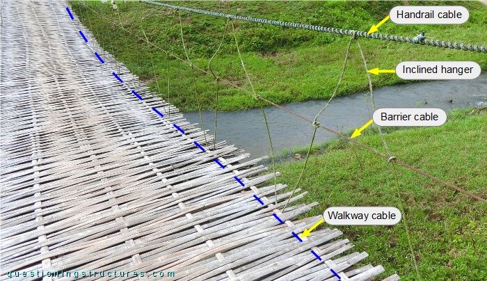
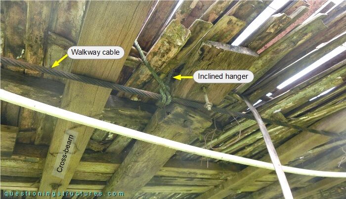
The inclined hangers are looped around the handrail as well as the barrier and walkway cables. Hanger slackness is noticeable. Figure 6 shows a bottom view of the bridge.
When are inclined hangers in suspended bridges feasible?