General Information
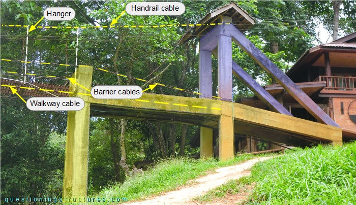
Figure 1 shows a suspended bridge that is used by motorcycles, bicycles and pedestrians.
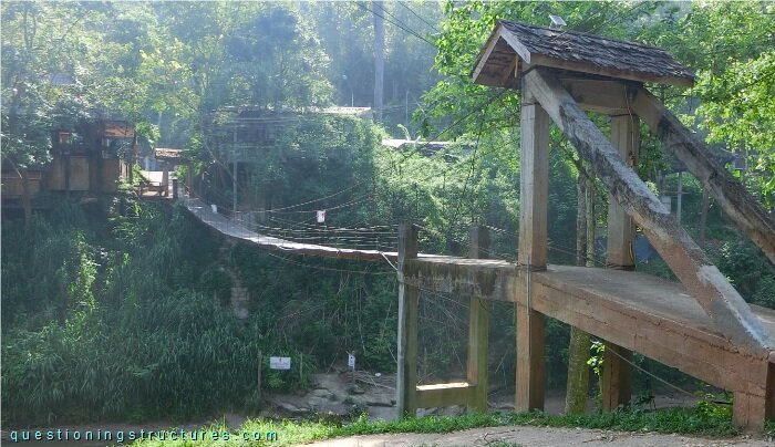
| Tower-to-tower distance | ≅ 35 m |
| Width | ≅ 1 m |
| Tower | Reinforced concrete |
| Girder | Steel transverse built-up section |
| Number of walkway cables | 3 |
Bridge Configuration
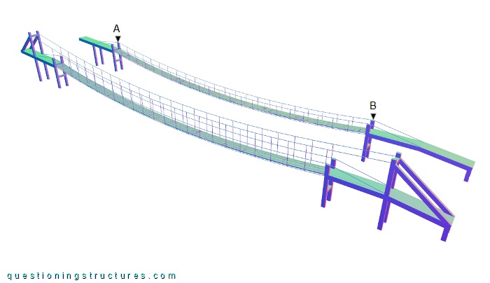
Figure 2 shows a schematic lateral view of the bridge.
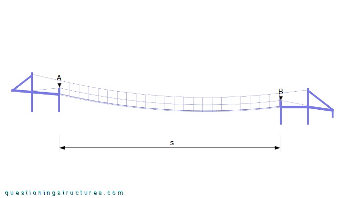
The span s ≅ 35 m, and the height difference between A and B is about 2 meters.
Figure 3 shows a schematic cross-section of the bridge.
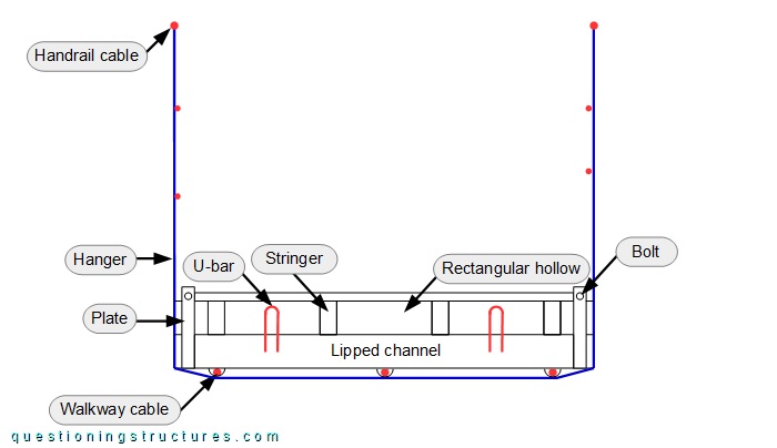
The built-up girder consists of two side-by-side placed lipped channels over which are placed two side-by-side placed rectangular hollow sections. The lipped channels and the rectangular hollow sections are connected by U-bars and plates; the former are welded, while the latter are welded in the bottom region and bolted in the top-end region. The girder spacing is about 1.5 meters, and the stringers are non-stacked. The hangers are made of steel wire ropes; they run under the walkway cables (direct contact), touch the bottom edges of the lipped channels, and are connected to the two handrail cables. Figure 4 shows a bottom view of the bridge.
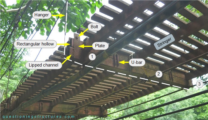
The walkway cables are marked by the numbers.
Figure 5 shows a tower.
The cables are anchored to the tower, which consists of a bottom (yellow background) and an upper (blue background) unit. Figure 6 shows a schematic lateral view of the bridge and an alternative variant.
The towers of the alternative variant do not have the upper unit.
What is a possible cross-section of the alternative variant?