General Information
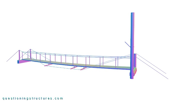
Figure 1 shows a pedestrian suspended bridge.
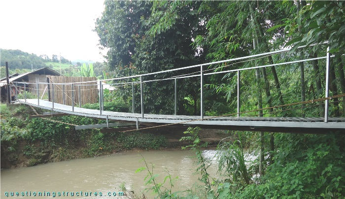
| Tower-to-tower distance | ≅ 15 m |
| Width | ≅ 1 m |
| Towers | Steel and RC (shore 1); wood log, timber, and a tree (shore 2) |
| Girder | Steel transverse beam |
| Number of walkway cables | 2 |
Structural Concept
Figure 2 shows the bridge.
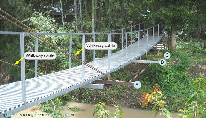
The girders (A, B, and C) have a length of about 2.5 m, and their bottom sides are directly connected to the walkway cables, which are made of steel wire ropes. Figure 3 shows a bottom view of the bridge.
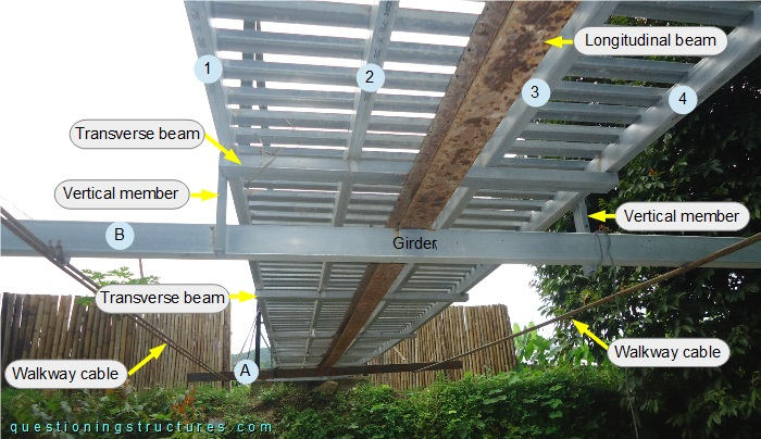
Over the girders are stacked a longitudinal beam (at mid-width), transverse beams, four stringers (1 to 4), and the deck. The side stringers (1 and 4) are connected to the girders by vertical members. The longitudinal beam is made of a rusted H-section, while the remaining parts are made of square hollow sections; they are connected by welding. Figure 4 shows the bridge entrance on shore 1.

The tower's columns (A1 and B1) are made of H-sections of different heights (A1 is shorter than B1), and their bases are embedded in RC. The walkway cables pass over the top end of column A and through two web holes on column B; they are anchored (on both shores) to ground-embedded anchor blocks. Figure 5 shows the opposite bridge entrance.

Column A2 is made of a wood log (ground-embedded base), and the walkway cable passes over its top end; column B2 is made of a living tree, and the walkway cable is connected to it by a vertical cable (steel wire rope). Figure 6 shows the connection between the walkway cable and the living tree.
| Walkway cable to vertical cable | Vertical cable to tree |
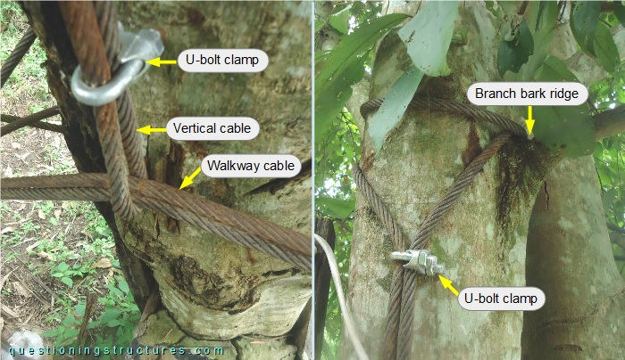
The walkway cable is directly connected to the vertical cable, which is looped around the trunk over a branch bark ridge and terminated with U-bolt clamps. Figure 7 shows a schematic three-dimensional view of the bridge.
Alternative Variant
Figure 8 shows a schematic three-dimensional view of the bridge and a pony truss bridge variant made of steel.
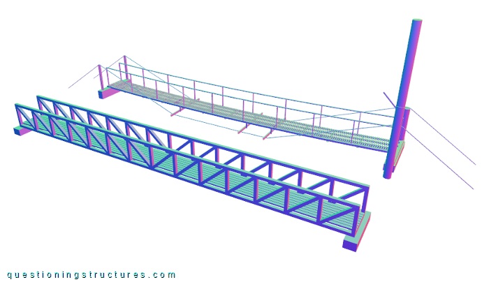
Which bridge structural behavior can probably be predicted more precisely and simply?