General Information
Figure 1 shows a suspension bridge that is used by motorcycles, bicycles and pedestrians.
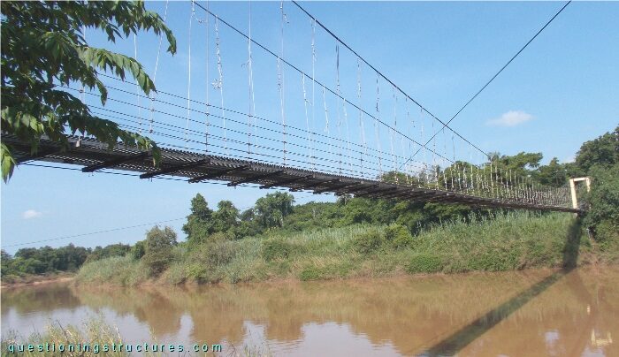
| Type | Single-span suspension bridge |
| Main span | ≅ 110 m |
| Deck width | ≅ 2 m |
| Deck width to main span ratio | ≅ 1:55 |
| Pylon | Reinforced concrete |
| Girder | Timber transverse beam |
Hanger Cable to Main Cable Connection
Figure 2 shows a hanger cable to main cable connection.
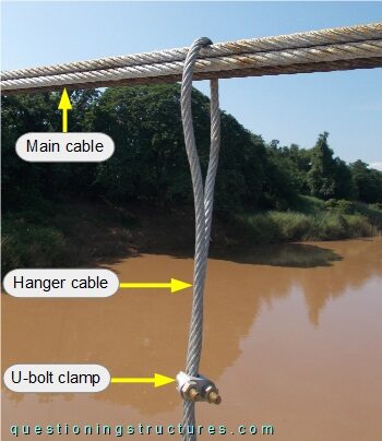
The hanger cable passes over the main cable and is fixed with a single U-bolt clamp.
Figure 3 shows two further connections.
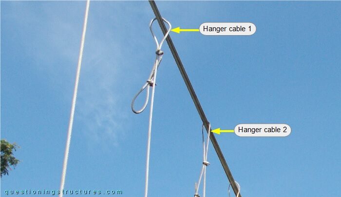
Slackness of hanger cable 1 is noticeable.
What are the main structural consequences?
Figure 4 shows a hanger cable top-end region.
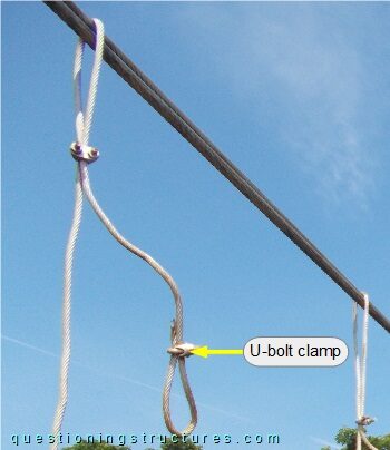
The dead-end is bent (approximately 180 degrees) and fixed with a single U-bolt clamp.
Hanger Cable to Stringers Connection
The hanger cables are connected to the timber girders, except for the hanger cable indicated in figure 5.
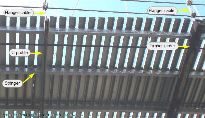
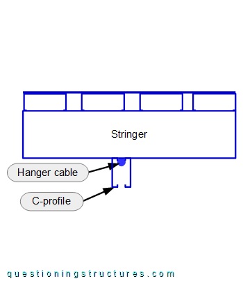
The hanger cable passes between two C-channels and is directly connected to the stringers. A schematic section of the hanger cable to stringer connection is shown in figure 6.
What are the main structural consequences?
How much bending stiffness does a C-channel require?