General Information
Figure 1 shows a suspension bridge that is used by motorcycles, bicycles and pedestrians.
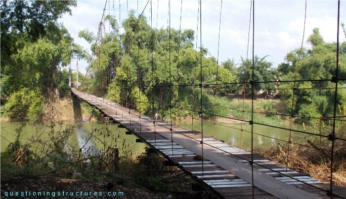
| Type | Single-span suspension bridge |
| Main span | ≅ 110 m |
| Deck width | ≅ 2 m |
| Deck width to main span ratio | ≅ 1:55 |
| Girder | Timber and steel transverse beams |
| Pylon | Reinforced concrete |
Connection Between Hanger Cable and Main Cable
Figure 2 shows a hanger cable to main cable connection.
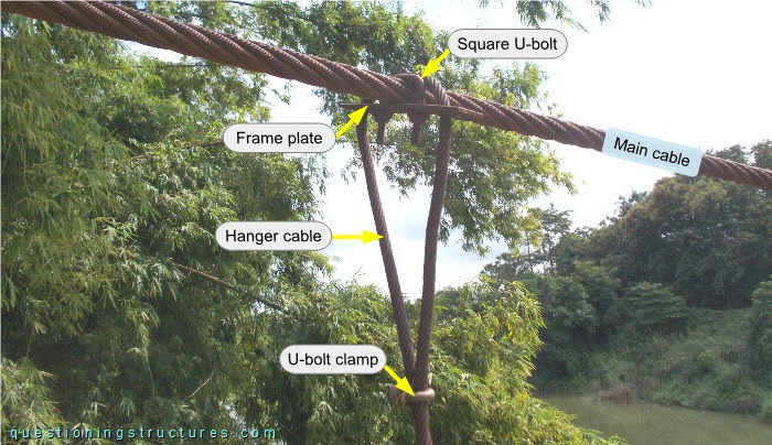
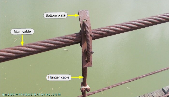
The hanger cable passes over the main cable and through a two-hole frame plate, which lies horizontally and connects to the main cable by a square U-bolt and nuts. The hanger cable termination consists of U-bolt clamps. Figure 3 shows a connection where the frame plate is in a vertical position.
What are the main structural consequences?
Figure 4 shows hanger cables in the pylon region.
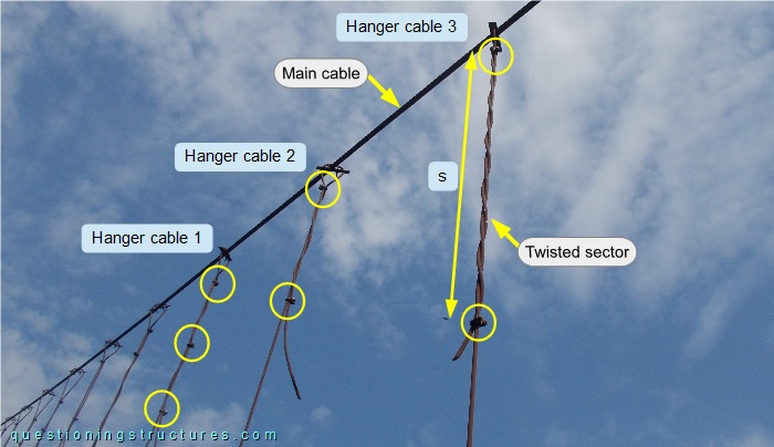
The frame plates of hangers one to three are in a horizontal position. Hanger 1 has three U-bolt clamps (marked by the circles), while hangers 2 and 3 have two U-bolt clamps; they are placed apart at different distances (s), and the dead end is twisted on the live end between the U-bolt clamps.
How does the termination affect the structural behavior of the hanger cable?
Figure 5 shows a regular hanger with an additional hanger placed next to the regular one.
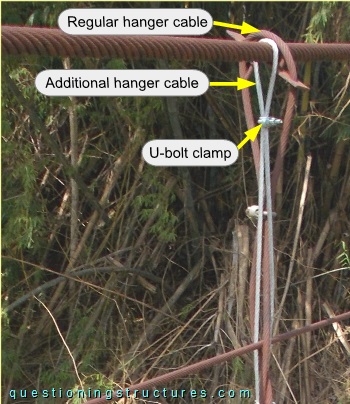
The additional hanger cable has a smaller diameter and is without a frame plate and a square U-bolt.
Main Cables
Figure 6 shows a main span sector.
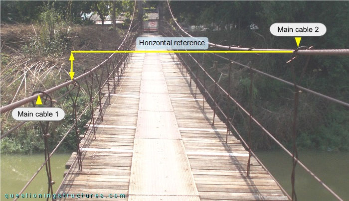
Main cable 1 is at a different elevation than main cable 2.
What are the main structural consequences?