General Information
Figure 1 shows a suspension bridge that is used by motorcycles, bicycles and pedestrians.
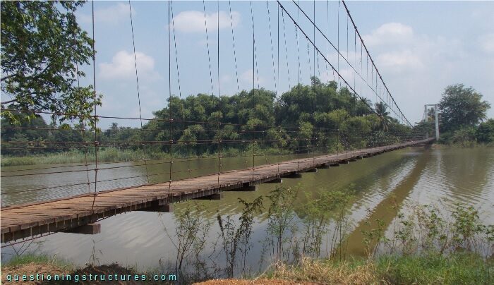
| Type | Single-span suspension bridge |
| Main span | ≅ 140 m |
| Deck width | ≅ 2 m |
| Deck width to main span ratio | ≅ 1:70 |
| Pylon | Reinforced concrete |
| Girder | Timber transverse beam |
Hanger Cable to Timber Girder Connection
Figure 2 shows a schematic cross-section of the bridge.
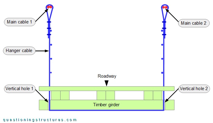
A single hanger cable runs from main cable 1 to main cable 2 via the timber girder bottom side. The hanger cable passes through the timber girder through two vertical holes. The forces are transferred by direct (cable to timber girder) contact. Figure 3 shows a hanger cable to timber girder connection viewed from below.
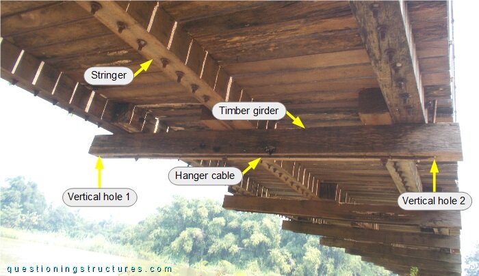
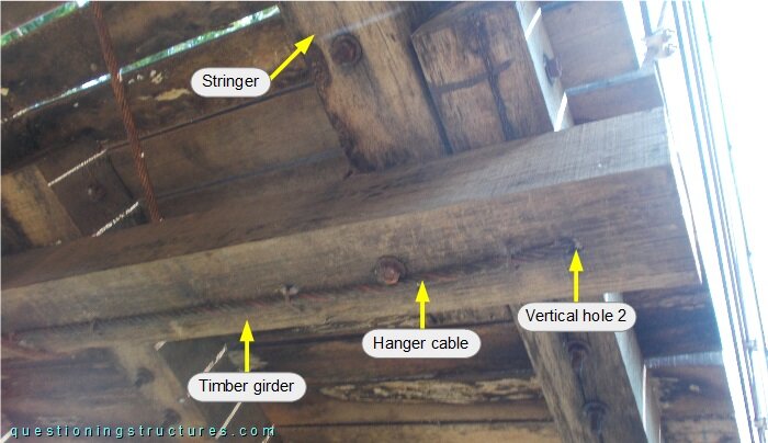
Figure 4 shows a further connection in the vertical hole region.
What are other possible solutions?