General Information
Figure 1 shows a pedestrian suspension bridge.
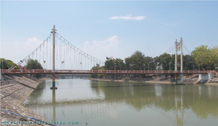
| Type | Three-span suspension bridge |
| Main span | ≅ 50 m |
| Deck width | ≅ 2.5 m |
| Deck width to main span ratio | ≅ 1:20 |
| Pylon | Steel and reinforced concrete |
| Girder | Steel twin H-girder |
Turnbuckles
Figure 2 shows a schematic lateral view of the bridge.
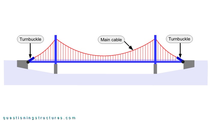
Each main cable is connected to two turnbuckles. Figure 3 shows a side view of a turnbuckle.
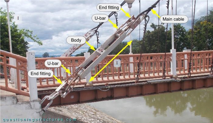
The turnbuckles are of type open body; they are individual parts productions and are made of wide flat bars, circular hollow sections, threaded rods, and U-bars. The body has a length of l ≅ 1.2 m. Figure 4 shows a turnbuckle viewed from below.
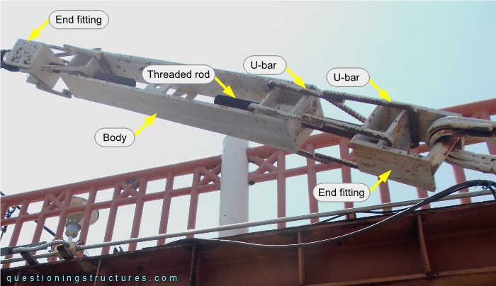
The body is connected to the end fittings by the threaded rods and the U-bars, which are overlapping and joined by welding. Figure 5 shows the top region of a main span lamp.
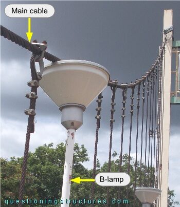
The main cable touches the lamp, and the hanger cables are near the lamp.
Suppose to tighten the turnbuckles. What needs to be considered and inspected before the tightening process?
Hanger Cable to H-Girder Connection Failure
Figure 6 shows a schematic cross-section of the hanger cable to H-girder connection.
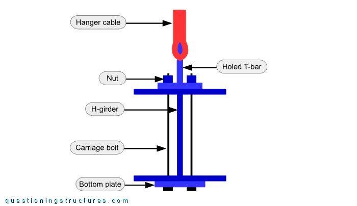
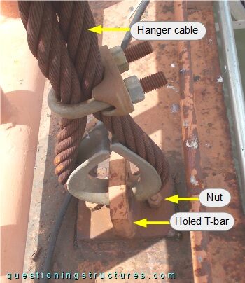
The connection consists of a short built-up T-section, two carriage bolts, a two-hole plate, and two nuts. The short T-section is placed over the upper flange and has three holes (one horizontal and two vertical), and the two-hole plate is placed under the bottom flange. The short T-section and the two-hole plate are connected by the carriage bolts and the nuts. The hanger termination consists of U-bolt clamps and a wire rope thimble, which passes through the horizontal hole of the short T-section. Figure 7 shows a hanger cable to H-girder connection viewed from above and from below, while figure 8 shows a failed connection.
| Viewed from above | Viewed from below |
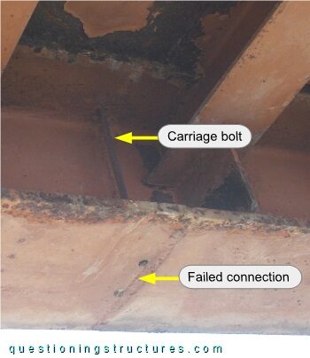
The carriage bolt failed; the failure is located on the bottom flange outer side level.
Does this failure affect the safety of the bridge?