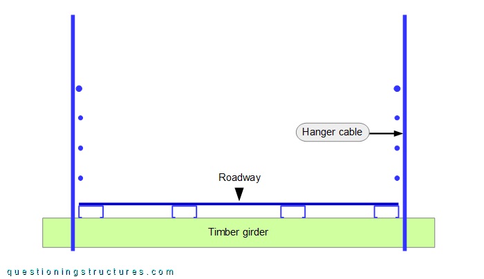
General Information
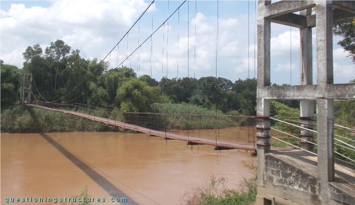
Figure 1 shows a suspension bridge that is used by motorcycles, bicycles and pedestrians.
| Type | Single-span suspension bridge |
| Main span | ≅ 95 m |
| Deck width | ≅ 1.5 m |
| Deck width to main span ratio | ≅ 1:63 |
| Pylon | Reinforced concrete (A-type, longitudinal) |
| Girder | Timber transverse beam |
Hanger Cable to Main Cable Connection
Figure 2 shows a hanger cable to main cable connection.
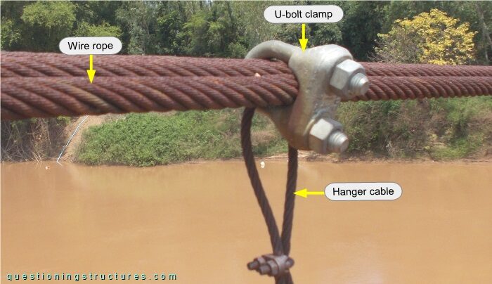
A main cable consists of three side-by-side placed steel wire ropes that are bundled by U-bolt clamps. The hanger cable is connected to the main cable by the same U-bolt clamp; the hanger cable does not pass over the main cable.
Main Cables
Figure 3 shows the main cables in the main span region.
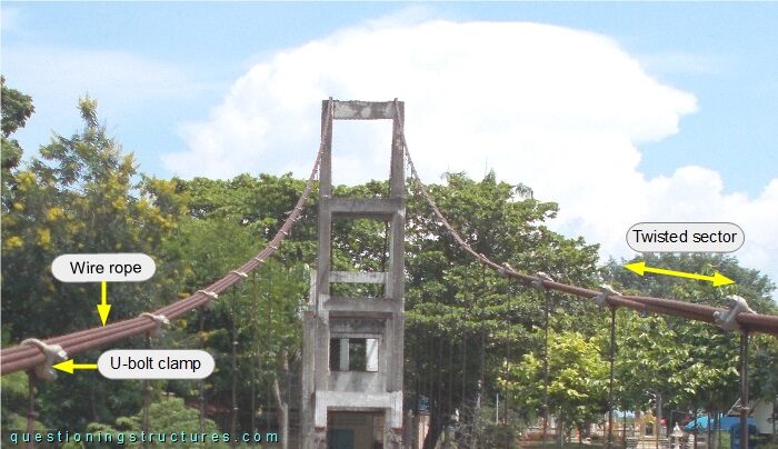
A twisted sector on the right main cable is noticeable.
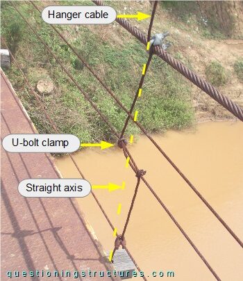
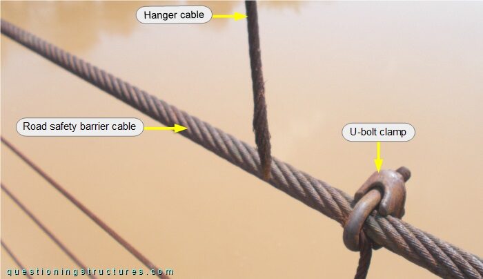
Hanger Cables
Figure 4 shows a hanger cable.
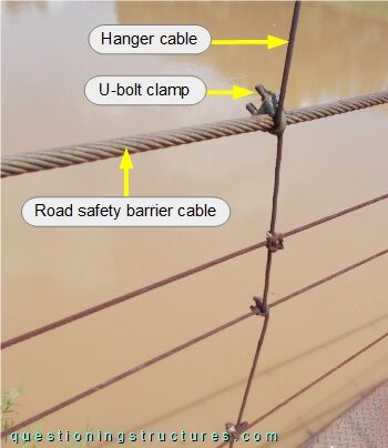
The hanger cables are also connected to the road safety barrier cables by U-bolt clamps. Figure 5 shows a further hanger cable.
Hanger Cable Failure
Figure 6 shows a failed hanger cable.
The hanger cable failed in the U-bolt clamp region.
What are the main structural consequences?
Hanger Cable to Timber Girder Connections
Figure 7 shows a schematic cross-section of a hanger to girder connection.
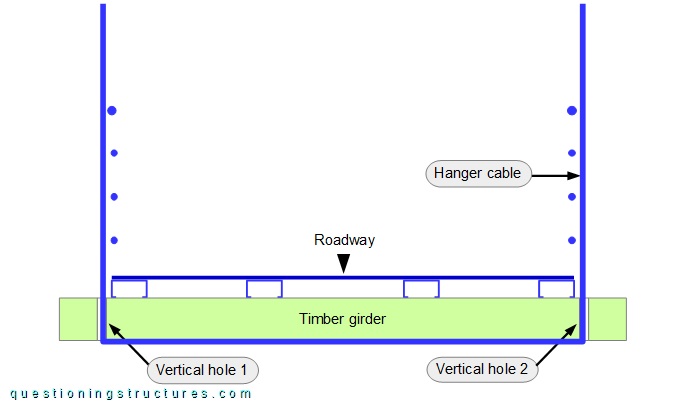
A single hanger cable runs under the girder's bottom side and passes through two vertical holes (1 and 2); the forces are transferred by direct (cable to girder) contact. The stringers are made of lipped channels, and the roadway is made of steel checker plates. Figure 8 shows vertical hole 1 region viewed from above.
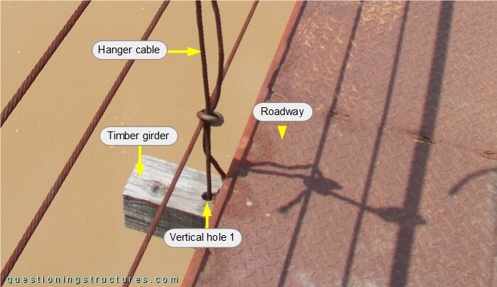
Figure 9 shows a further connection viewed from above.
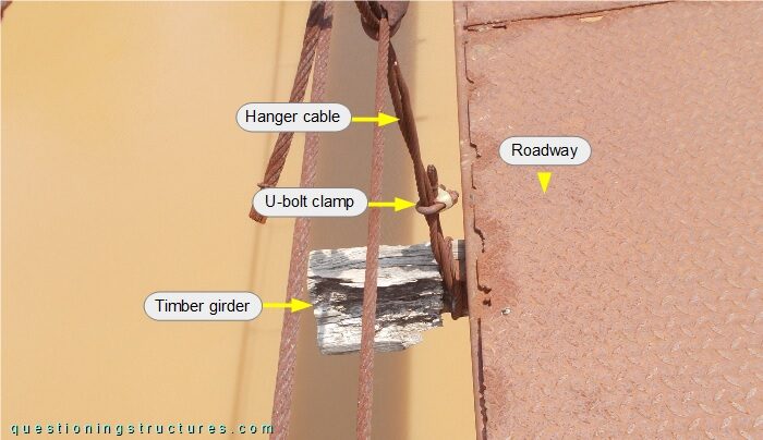
The hanger cable is wrapped around the girder, which has a reduced cross-section, and fixed with a single U-bolt clamp. Figure 10 shows a schematic cross-section of the above shown connection.