General Information
Figure 1 shows a suspension bridge that is used by motorcycles, bicycles and pedestrians.
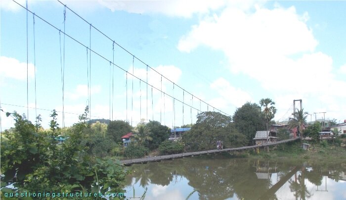
| Type | Single-span suspension bridge |
| Main span | ≅ 100 m |
| Deck width | ≅ 2 m |
| Deck width to main span ratio | ≅ 1:50 |
| Pylon | Reinforced concrete |
| Girder | Timber transverse beam |
Pylon Deformation
Figure 2 shows a pylon.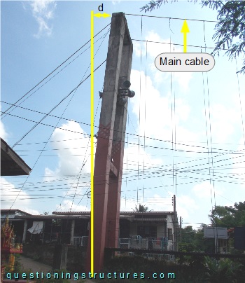
The double red arrow marks the pylon-top horizontal displacement (d).
Figure 3 shows the pylon top region.
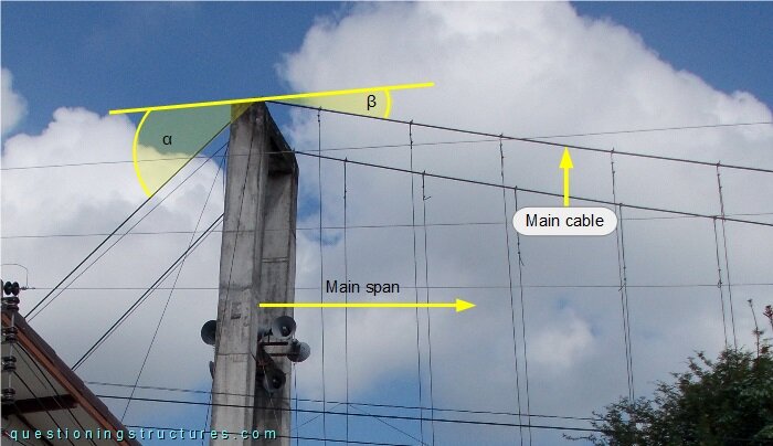
The main cable inclination angle α is greater than the inclination angle β.
Main Cable Anchorage
Figure 4 shows a main cable anchorage.
| Front view | Enlarged front view |
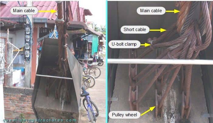
The main cable is connected to the anchor block by short cables (fixed by U-bolt clamps) and embedded anchor rods; the non-embedded parts are terminated with wire rope sheaves. The main cable and the short cables are connected directly (cable-to-cable connection).
Stringers
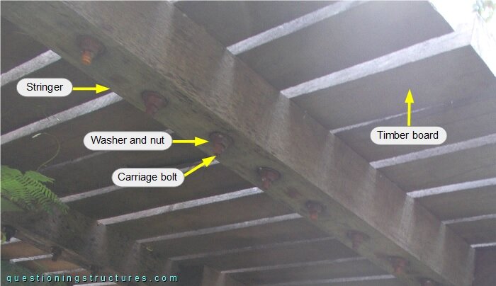
Figure 5 shows a deck sector.
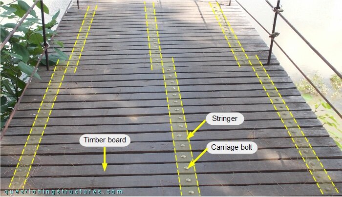
The deck consists of timber planks that are connected to the stringers by carriage bolts, washers and nuts. Figure 6 shows a main span sector viewed from below.